YitaHome TLCFLS-1003 Bedienungsanleitung

ASSEMBLY INSTRUCTIONS
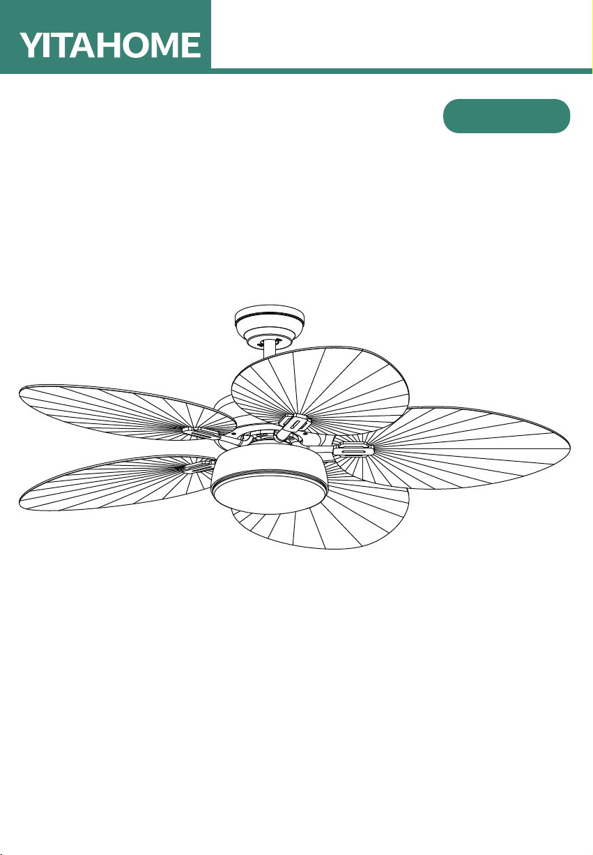
CEILING FAN WITH LIGHT
TLCFLS-1003

1
: 888-717-8084
If you have any questions about the installation of YITAHOME
products, just contact us from Monday to Friday 8:00 AM - 4:30 PM PST,
and Saturday 8:00 AM - 12:00 PM PST.
Alternative method to contact us (amazon.com orders only)
1. Log into your Amazon account
2. Go to "Your Orders" and find the purchase
3. Click on "Contact Seller"
CONTACT US:
ASSEMBLY INSTRUCTIONS
Thank you for selecting this product. Before use,please carefully
read this operation manual to understand the correct use of this
product.
Special attention should be paid to important safety warnings
and the operation manual should be kept for reference.
Note : our company reserves the right to improve the product
and instructions contained therein which may be changed
without notice.
The appearance of the product depends on the material of
the object.

2
ASSEMBLY INSTRUCTIONS
SAFETY GUIDELINES
BEFORE YOU START
1. To avoid possible electric shock, turn off the electricity in the main fuse box or on the circuit panel before you begin
the fan installation, maintain the fan or install any accessories.
2. Read all instructions and safety guidelines carefully before installing your fan and follow all the instructions.
3. Make sure all electrical connections comply with the local codes or ordinances and the national electrical code. If you
are unfamiliar with electric wiring, please consult a qualified licensed electrician.
4. Make sure you have a location that has clear space for the fans’ blades to rotate. There is at least seven (7) feet of
clearance between the floor and the fan blades’ tips. The fan should be mounted at least thirty (30) inches from
walls or other upright structures.
5. WARNING: The outlet box and ceiling support joist must be securely mounted, and capable of supporting at
least 100 pounds. To reduce the risk of fire, electric shock or personal injury, mount to the outlet box marked
“acceptable for fan support” and use mounting screws matching the outlet box. The box must be supported directly
by the building structure.
6. WARNING: To reduce the risk of fire, electric shock or personal injury, mount to the outlet box marked
"acceptable for fan support" and use mounting screws matching the outlet box. Most outlet boxes are only used for
supporting lighting fixtures and not acceptable for fan support. Consult a qualified electrician if in doubt.
7. Electrical diagrams are for reference only. Light kits don’t come with the fan. It must be UL listed and marked
“suitable for use with the fan model you are installing”. Switches must be UL. general switches. Refer to the
instructions to properly assemble the fan.
8. After installing, check that all connections are firmly secured.
9. After making electrical connections, the spliced conductors should be turned upward and carefully pushed up into
outlet box. The wires should be placed separate from the grounded conductor as well as the equipment-grounding
conductor on opposite side of the outlet box.
10. WARNING: To reduce the risk of electrical shock and fire, do not use this fan with any solid-state fan speed
control device, or rheostat.
11. Do not operate the reverse switch until the fan has come to a complete stop.
12. Do not insert anything into the fan’s blades while they are rotating.
13. WARNING: To reduce the risk of personal injury, do not bend the blade brackets (also referred to as "flanges")
during assembly or after installation. Do not insert objects between the blades.
14. To avoid personal injury or damage to the fan and other items, be cautious when working around or cleaning the
fan.
15. Do not use water or detergent to clean the fan or its blades. A dry or lightly dampened cloth will be more suitable.
NOTE: The important safety precautions and instructions on the manual are not meant to cover all possible conditions
and situations that may occur. It is understood that common sense and caution are necessary factors during
installing and operating the fan.
NOTE: This product is not intended for persons who have badly physical sensory or mental capabilities, or lack certain
life experience and knowledge, especially children. Unless such persons are supervised or trained to operate the
appliance under the guidance of a person who is responsible for their safety.
NOTE: Children should be supervised to ensure that they do not use appliances as toys.
NOTE: You must install a switch or circuit breaker that disconnects all power poles, at least 3 mm between each pole.
Contact a licensed electrician if you are not good at performing electrical work. It’s the licensed electrician who installs
the fan, if required by the local code. Do not use the fan with a dimmer switch. Turn off power at breaker.
!
!
!
!

BEFORE YOU START
Product Instruction
3
ASSEMBLY INSTRUCTIONS
Tools and Materials Required
SCREWS BAG
Contact a licensed electrician if you
are not good at performing electrical
work. It’s the licensed electrician
who installs the fan, if required by
the local code. Do not use the fan
with a dimmer switch. Turn off
power at breaker. External Hexagonal
Wrench
Wire Stripper Phillips
Screwdriver
Step Ladder
OFF
OFF
ST5x35
Setscrew
4 pcs
Expansion
Screw
2 pcs
Setscrew Stopper
4 pcs
Wire
Connectors
3 pcs
#8-32
Setscrew
2 pcs
Screw
Washer
2 pcs
Screw Spring
Washer
2 pcs
Balance Pack
1 pc
Fabric
Washer
16 pcs
Screws
for Blades
16 pcs
Remote Control
and Receiver
Blades
Mounting Bracket
ST5x35 Setscrew
Downrod
Canopy
M4x14 Screws
Coupling Cover
Hairclip Pin
Fan Motor Assembly
Blade Bracket
Light Kit Screws for Blade Bracket
Lamp Shade
Clevis Pin
MED
1H
STOP
LOW
LIGHT
HI
ON/OFF
2H
4H
8H

4
ASSEMBLY INSTRUCTIONS
INSTALLING THE FAN
INSTALLING THE MOUNTING BRACKET
The ceiling fan must be installed in the location where there is 12"(300mm) spacing from the tips of all blades to the
nearest objects or walls. REMEMBER to turn off the power before hanging the fan. Follow the instruction below to
hang your fan properly:
1. For concrete ceiling, drill two holes in the ceiling and secure the mounting bracket to the ceiling with two
0.32"(8mm) (distance between the two holes should be appropriate) expansion screws, flat washers nuts
provided and tighten with a spanner.
2. For wood ceiling, secure the mounting bracket to the ceiling that is capable of carrying a load of at least 100lbs
(45kgs) with two long mounting screws and washers provided. Be sure at least 0.12"(30mm) of the screw is
threaded into the support.
3. For installing the outlet box, secure it directly to the building structure. Use appropriate fasteners and building
materials. The outlet box and its support must be able to fully bear the moving weight of the fan (at least 100lbs).
Use a UL listed metal outlet box instead of plastic ones. Figure 1& 2 show the examples of mounting the outlet box.
Tools Required: Phillips screwdriver, a pair of pliers, straight slot screwdriver, adjustable wrench, step ladder,
and wire cutters.
CELING JOIST
CEILING JOIST
CROSS BRACE
OUTLET BOX
PARALLEL WOOD BRACE
(MIN.2" THICK)
OUTLET BOX
CEILING JOISTOR
CROSS BRACE

ASSEMBLY INSTRUCTIONS
5
4.Refer to the Fig. on the right to mount when the ceiling is angled (Max. 15°).
NOTE: The hanger must be able to withstand the weight of 100lbs (45kgs) or more after the installation
Before installing fan blades, remove the motor’s fastener that is only used to protect the motor from damages in transit.
1) Attach blade brackets to blades with the blade bracket screws and metal or fabric washers.
2) Attach the blade assembly to the provided screws and tighten them.
15
INSTALLING THE BLADE
1) 2)
Dismantle
Reserve

6
ASSEMBLY INSTRUCTIONS
REMEMBER to turn off the power before hanging the fan. Follow the steps below to hang your fan properly:
1) Remove the hair clip pin “1” and clevis pin “2” on the fan motor’s downrod joint, then withdraw half of the screw
“3” that locks the downrod.
2) Loosen the screws “5” and “6” on the downrod and remove the lifting ball and safety pin “4”.
3) Pass the detached downrod through the wire and insert it into the downrod joint. Make sure that it is aligned with
the hole on the joint. Pass through clevis pin “2” and insert the hair clip “1” into the hole of clevis pin “2”, then
lock the downrod with the screw “3”.
4) Pass the canopy through the downrod.
5) Pass the detached lifting ball through the downrod, then insert safety pin “4” to jam the lifting ball, and then use
screws “5” and “6” to lock it.
INSTALLING THE DOWNROD
INSTALLING THE FAN TO MOUNTING BRACKET ON CEILING
WARNING: To avoid possible electrical shock, be sure the electricity is
turned off in the main fuse box before wiring.
Carefully lift the fan assembly onto mounting bracket and rotate the fan
until the notch on downrod ball “1" engages the ridge on the mounting
bracket “2".
This will allow for hands free wiring.
1
2
!
1) 2) 3)
4) 5) 6)
5
4
6
54
6
1
2
3
1
2
3

7
ASSEMBLY INSTRUCTIONS
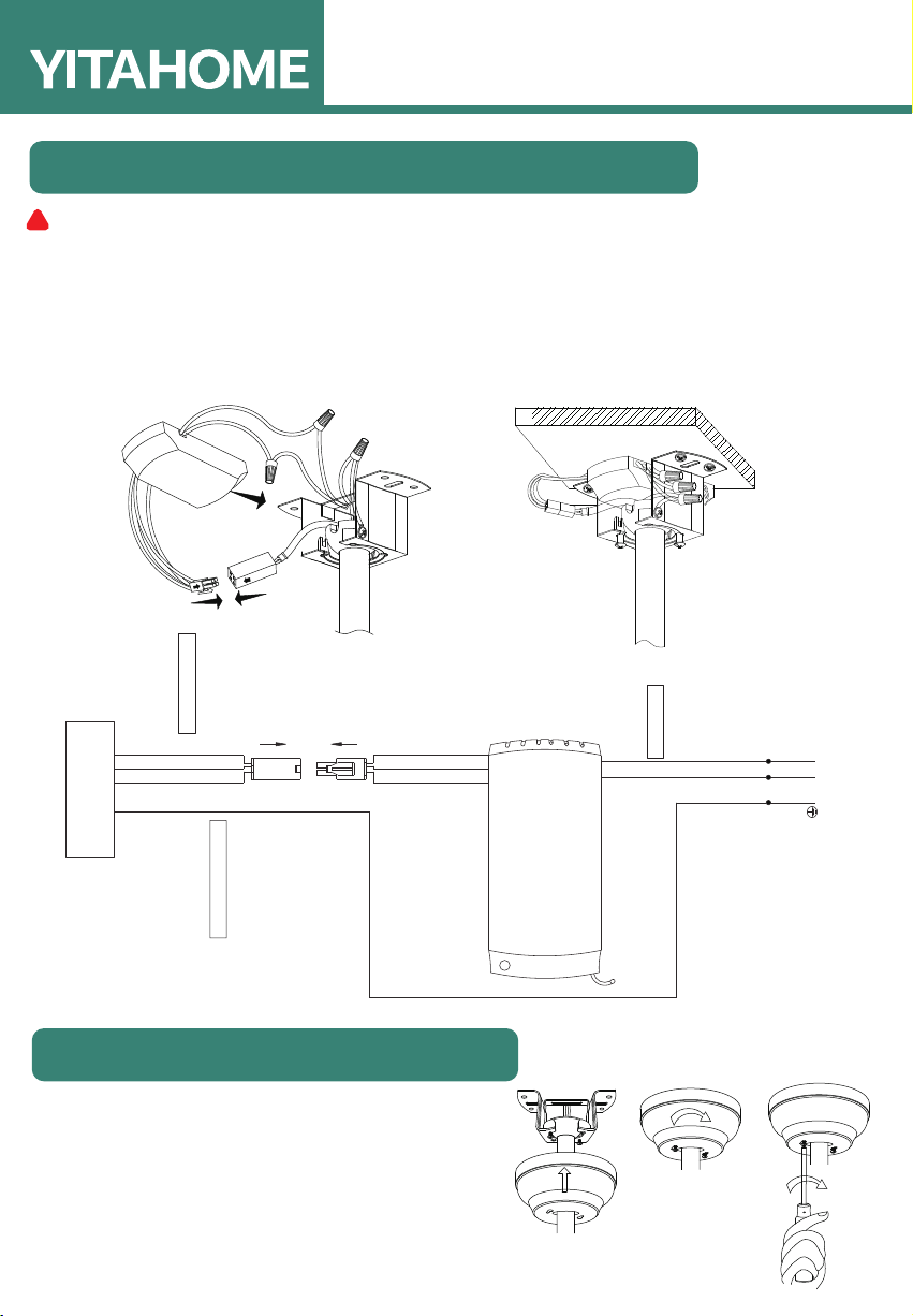
WARNING: To avoid possible electrical shock, be sure the electricity is turned off in the main fuse box before wiring.
Loosen the 2 screws on the bottom of mounting bracket
but do not remove them. Raise the canopy up and align the
keyholes on the bottom of the canopy with the 2 screws on
the bottom of mounting bracket.
Rotate the canopy until both screws from the mounting
bracket drop into the slot recesses. Tighten screws.
1. Connect the fan to the remote control. The fan’s 4P plug should insert into the the remote control’s 4P plug.
2. Connect the remote control to the house’s power line, then connect the remote control’s white wire to the
house’s white wire. Connect the remote control’s black wire to the house’s black wire, and connect all the
fans’ green ground wires to the house of ground wires. Secure wires.
3. Connect the fan motor to the lamp: connect the fan motor’s 1P white wire to the lamp’s 1P white wire. Connect
the fan motor’s 1P blue wire to the tool’s 1P blue wire.
MAKE THE ELECTRIC CONNECTIONS
INSTALLING THE CANOPY
Motor
green
FOR MOTOR blackO
to the FAN MOTOR
to the FAN LIGHT
receiver of
remote
control
4P
to AC Power
brown
ACIN N
AC IN L
green
120 Vac
SUPPLY
AC N
AC L
blue
green
FOR MOTOR/LIGHT N white
FOR LIGHT L blue
4P
TO MOTOR blackO
TO MOTOR/LIGHT N white
TO LIGHT L blue
green
!

8
ASSEMBLY INSTRUCTIONS
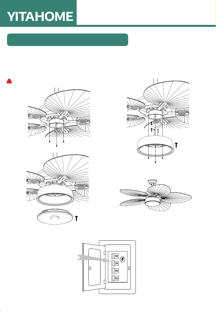
1.Remove 3 mounting screws from the light kit.
2.Find the Molex connector from the motor and the Molex connector from the light kit. Slide them together.
3.Install 3 screws to the motor’s junction box and light kit tightly.
4.Carefully install the glass shade into the main body and turn clockwise to lock.
WARNING: Take care not to over tighten when installing the glass shade.
Installation is now finished. Turn on the power switch as Fig 7. Then the fan lights are on. Test and pair your fan
immediately using the remote control.
INSTALLING THE LIGHT KIT
!
12
34

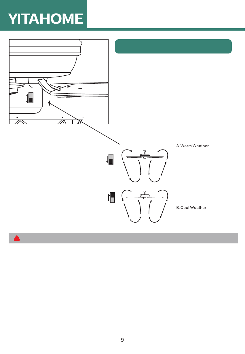
Turn on the power and check the operation of the fan.
The fan pull chain controls the fan speed as follows:
1 pull-High, 2 pulls-Medium, 3 pulls-Low, 4 pulls-Off
The appropriate speed settings of warm or cool weather
depend on many factors such as the room size, ceiling height,
and the number of fans.
The slide switch (XX) controls the direction of the blades:
forward (switch down) or reverse (switch up).
A. Warm weather-(Forward) A downward airflow creates a cooling effect. This allows you to set your air conditioner
on a higher setting without affecting your comfort.
B. Cool weather-(Reverse) An upward airflow moves warm air off the ceiling.This allows you to set heating unit on a
lower setting without affecting your comfort.
OPERATING YOUR FAN
ASSEMBLY INSTRUCTIONS
(WINTER TIME)
(SUMMER TIME)
NOTE:Wait for the fan to stop before reversing the direction of the blade rotation
!
Inhaltsverzeichnis
Andere YitaHome Lüfter Handbücher

YitaHome
YitaHome ZSWY-V1 Bedienungsanleitung

YitaHome
YitaHome TLCFLS-0009 Bedienungsanleitung

YitaHome
YitaHome TLCFLS-2007 Bedienungsanleitung

YitaHome
YitaHome ZSWYHS-V1 Bedienungsanleitung

YitaHome
YitaHome TLCFLS-1002 Bedienungsanleitung

YitaHome
YitaHome TLCFLS-2018 Bedienungsanleitung

YitaHome
YitaHome JMOMQ-V1 Bedienungsanleitung

YitaHome
YitaHome TLCFLS-0008 Bedienungsanleitung

YitaHome
YitaHome TLCFLS-0010 Bedienungsanleitung

YitaHome
YitaHome TLCFLS-2022 Bedienungsanleitung