
Zehnder Rittling ComfoSpot 50 Kurzanleitung
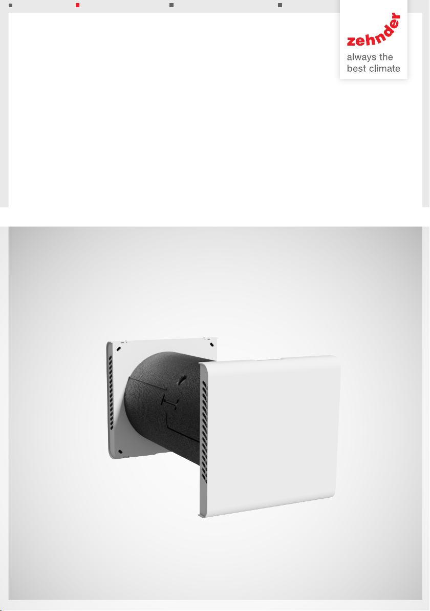
ComfoSpot 50
Zubehör Wandeinbaurohr rund
Round mounting block
Accessoire Tube de montage mural rond
Accessorio tubo rotondo per montaggio a parete
Toebehoren mantelbuis rond
Przejście okrągłe do montażu w ścianie
Montagehinweise - Installation notes - Instructions de montage - Indicazioni per
il montaggio - Montageaanwijzingen - Wskazówki dotyczące montażu
Decorative radiators Comfortable indoor ventilation Heating and cooling ceiling systems Clean air solutions

2
Alle Rechte vorbehalten.
Die Zusammenstellung dieser Bedienungsanleitung erfolgte mit größter Sorgfalt. Dennoch haftet
der Herausgeber nicht für Schäden aufgrund von fehlenden oder nicht korrekten Angaben in dieser
Bedienungsanleitung. Bei Meinungsverschiedenheiten ist der deutsche Originaltext letztendlich
verbindlich.
All rights reserved.
This manual has been compiled with the utmost care. However, the publisher cannot be held liable
for any damage caused as a result of missing or incorrect information in this manual. In case of
disputes the German version of these instructions will be binding.
Tous droits reserves.
Ce manuel a ete compose avec le plus grand soin. L‘editeur ne peut neanmoins pas etre tenu
responsable de dommages decoulant d‘informations manquantes ou erronees dans ce manuel. En
cas de différend, seule la version allemand de ce mode d’emploi est contraignante.
Tutti i diritti riservati.
La presente documentazione e stata redatta con la massima attenzione. L‘editore non
puo comunque essere ritenuto responsabile di eventuali danni derivanti dalla mancanza o
dall‘inesattezza delle informazioni qui fornite. In caso di disaccordo, il testo tedesco leader.
Alle rechten voorbehouden.
Bij de samenstelling van deze handleiding is uiterste zorg betracht, de uitgever kan echter niet
verantwoordelijk worden gehouden voor enige schade ontstaan door het ontbreken of onjuist
vermelden van informatie in deze handleiding. In geval van onenigheid is de Duits tekst leidend.
Wszelkie prawa zastrzeżone.
Niniejsza instrukcja obsługi została sporządzona z najwyższą starannością. Wydawca nie ponosi
odpowiedzialności za jakiekolwiek szkody powstałe na skutek nieumieszczenia w niej informacji lub
umieszczenia w niej nieprawidłowych informacji. W przypadku sporów wiążąca jest wersja niniejszej
instrukcji w języku niemiecki.

3
Montageanleitung: Zubehör Wandeinbaurohr rund ..........................................................
Installation notes: Round mounting block .........................................................................
Instructions de montage: Accessoire Tube de montage mural rond .................................
Indicazioni per il montaggio: Accessorio tubo rotondo per montaggio a parete ................
Montageaanwijzingen: Toebehoren mantelbuis rond ........................................................
Wskazówki dotyczące montażu: Przejście okrągłe do montażu w ścianie ........................
4-5
6-7
8-9
10-11
12-13
14-15

4
Wandeinbaurohr rund
Verwendungszweck
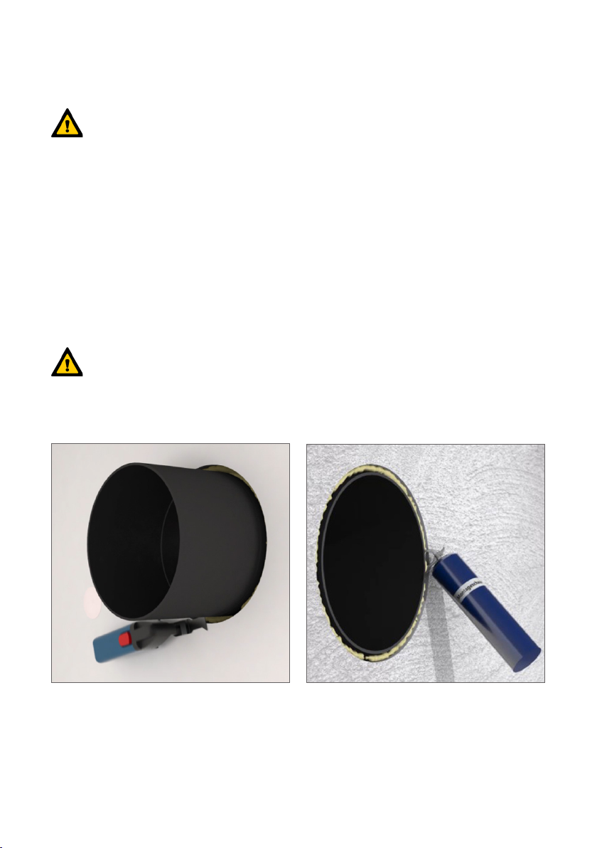
Das Wandeinbaurohr rund besteht aus
dem PVC-Wandeinbaurohr und zwei
Verschlussstopfen (Abb.1). Es dient zur
Aufnahme des Lüftungsgerätes ComfoSpot 50.
Für die Montage des PVC-Wandeinbaurohres
ist in der Außenwand eine Kernlochbohrung
ø 340 mm vorzusehen. Die nale Wanddicke
muss im Bereich von min. 335 mm bis
max. 600 mm liegen.
Vorbereitungsarbeiten
Wählen Sie einen passenden Montageort in
einer Außenwand. Achten Sie darauf, dass für
die bestimmungsgemäße Funktionsweise des
Lüftungsgerätes raumseitig seitlich links 39
und rechts 29 cm zum Bohrzentrum und für
Wartungsarbeiten 70 cm frontseitig Freiraum
einzuhalten sind.
Kernlochbohrung
Voraussetzung für eine ordnungsgemäße
Installation des ComfoSpot 50 sind lotrechte
Wände.
Für die Kernlochbohrung ist auf eine
waagerechte Achse des Bohrloches zu
achten (Abb.2).
Der Durchmesser der Bohrung muss
mindestens 340 mm betragen.
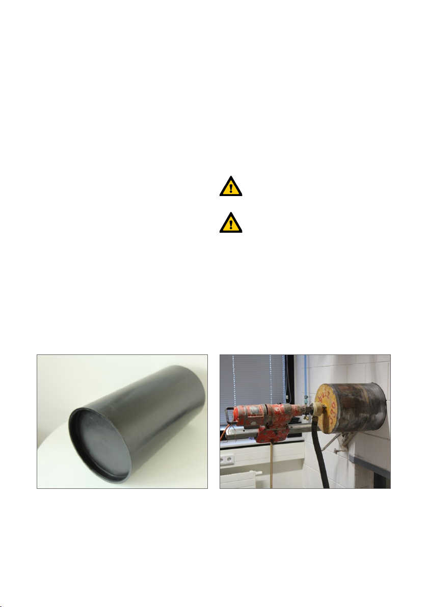
Abb.1 - Wandeinbaurohr Abb.2 - Kernlochbohrung
5
Wandeinbaurohr rund
Installation des
Wandeinbaurohres
Das Gerät ist in Feuchträumen nur
außerhalb der Schutzbereiche der
Zonen 1 und 2 gemäß DIN 57100/VDE 100 Teil
701 zu installieren!
Führen Sie das PVC-Wandeinbaurohr in
das Kernloch ein, und positionieren Sie es in
waagerechter Lage. Das PVC-Wandeinbaurohr
hat einen Außendurchmesser von 315 mm und
ist mit geeigneten Mitteln in der Bohrung zu
xieren. Zur Fixierung ist ausschließlich nicht
quellender Kleber oder Montageschaum zu
verwenden!
Beachten Sie dabei, dass die
Rohrachse ebenfalls waagerecht liegt
und die Kreisform des Rohres gewährleistet
bleibt (maximal zulässige Abweichung von der
Kreisform im Innendurchmesser des Rohres:
+/- 1,5 mm).
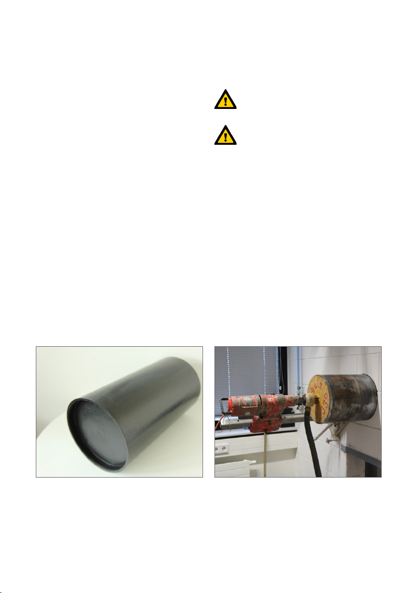
Vor Einbau des Lüftungsgerätes ist das PVC-
Wand-Einbaurohr so anzupassen, dass es
bündig zur Oberäche der Fassade bzw. der
Innenwand abschließt (Abb.3). Dazu ist das
PVC-Wand-Einbaurohr jeweils oberächenplan
zur fertigen Wand mit geeignetem Werkzeug
zu kürzen. Dichten Sie innen und außen den
Wandanschluss um das PVC-Wand-Einbaurohr
mit geeignetem Dichtmittel ab (Abb.4).
Setzen Sie nach der Montage die
Verschlussstopfen wieder beidseitig auf das
PVC-Wandeinbaurohr.
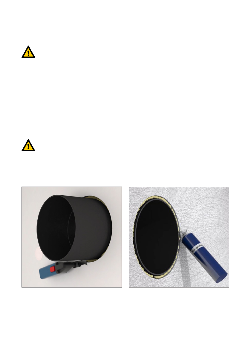
Abb.3 - PVC-Kernrohr einkürzen Abb.4 - Dichtmittel
6
Round mounting block
Intended use
The round mounting block consists of a PVC
mounting block and two dust covers (Fig. 1).
It is used to hold the ComfoSpot 50 ventilation
unit. A core hole of ø 340 mm (13 3/8 inch)
must be provided through the exterior wall for
installing the PVC mounting block. The nal wall
thickness must be within a range of min. 335 mm
(13 3/16 inch) to max. 600 mm (23 5/8 inch).
Preparatory work
Select a suitable installation location in an
exterior wall. Ensure that there is 39 cm
(15 3/8 inch) of clearance on the left side of
the room and 29 cm (11 7/16 inch) on the right
to the drilling centre and 70 cm (28 inch) deep
clearance in front to access the unit for routine
maintenance.
Core hole drilling
A plumb wall is required. (Fig. 2).
The cored hole must be level and
horizontal through the exterior wall.
The cored hole must be at least
340 mm (13 3/8 inch) in diameter.
Fig. 1 – mounting block Fig. 2 – core hole drilling

7
Round mounting block
Installation of the mounting
block
The location of the ComfoSpot 50
must meet all local and national code
requirements. Ensure that proper clearance is
provided to other xtures in bathrooms or other
"wet" rooms.
Install the mounting block into the wall opening
and ensure it is level. The mounting block has
an external diameter of 315 mm (12 3/8 inch)
and must be securely fastened in the wall
opening. Only non-expanding adhesive or low
expansion foam may be used to secure the
mounting block in the opening.
Throughout the installation process,
ensure that the pipe remains level and
round (the inside diameter of the pipe must not be
out of round by more than 1.5 mm (1/16 inch)).
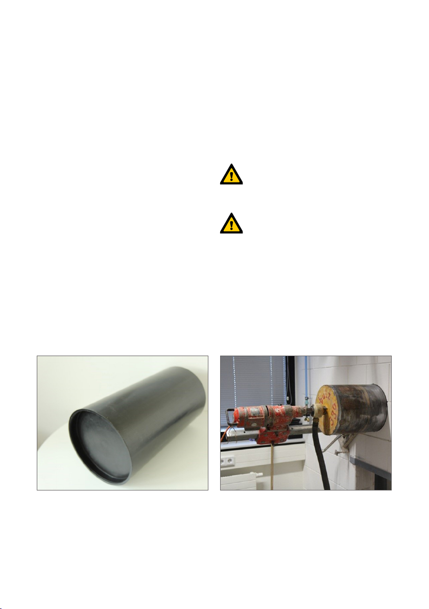
Before installing the ventilation unit, the
mounting block must be cut to length so that it
is ush with the surface of the façade and the
interior surface of the wall (Fig. 3). Seal the gap
between the wall opening and the mounting
block with suitable sealant at both the interior
and exterior (Fig. 4).
After the installation, reapply the dust covers
to both sides of the mounting block.
Fig. 3 – shortening the PVC pipe Fig. 4 – sealant
8
Tube de montage mural rond
Utilisation prévue
Le tube de montage mural rond se compose
du tube de montage mural en PVC et de
deux bouchons de fermeture (Fig. 1). Il sert
à l’installation de l’appareil de ventilation
ComfoSpot 50. Pour la mise en place du tube
de montage mural en PVC, un avant-trou d’au
moins 340 mm de diamètre doit être prévu
dans le mur extérieur. L’épaisseur nale du mur
doit être comprise entre 335 mm minimum et
600 mm maximum.
Travaux préparatoires
Sélectionnez un emplacement de montage
approprié dans un mur extérieur. Pour assurer
le fonctionnement correct de l’appareil de
ventilation, veillez à respecter un espace libre
côté pièce de 39 cm à gauche et de 29 cm
à droite par rapport au centre de l’avant-trou,
ainsi que de 70 cm vers l’avant pour les
travaux de maintenance.
Perçage de l’avant-trou
Des murs parfaitement verticaux sont la
condition requise pour garantir l’installation
correcte de l’appareil ComfoSpot 50.
Pour le perçage de l’avant-trou, veillez
à ce que le perçage suive un axe
horizontal (Fig. 2).
Le diamètre du perçage doit être
de 340 mm minimum.
Fig. 1 - Tube de montage mural Fig. 2 - Perçage de l’avant-trou
9
Tube de montage mural rond
Installation du tube
de montage mural
Dans les locaux humides, l’appareil
ne doit être installé qu’en dehors des
zones de protection 1 et 2 selon la norme
DIN 57100/VDE 100 Partie 701 !
Insérez le tube de montage mural en PVC dans
l’avant-trou et positionnez-le à l’horizontale. Le
tube de montage mural en PVC possède un
diamètre extérieur de 315 mm et doit être xé
dans l’avant-trou avec des moyens appropriés.
Pour la xation, utilisez exclusivement une colle
ou une mousse de montage qui ne gone pas.
Veillez à ce que l’axe du tube soit
également à l’horizontale et à ce
que la forme ronde du tube soit préservée
(divergence maximale admissible du diamètre
intérieur du tube par rapport à la forme ronde :
+/- 1,5 mm).
Avant le montage de l’appareil de ventilation,
le tube de montage mural en PVC doit être
ajusté, de sorte qu’il débouche à eur de
la surface de la façade et du mur intérieur
(Fig. 3). Pour ce faire, raccourcissez le tube de
montage mural en PVC avec un outil approprié,
de façon à ce qu’il afeure à la surface du mur
ni. Etanchéiez la zone de contact avec le
mur à l’intérieur et à l’extérieur en appliquant
un matériau d’étanchéité approprié autour du
tube de montage mural en PVC (Fig. 4).
Après le montage, remettez les bouchons de
fermeture en place des deux côtés du tube de
montage mural en PVC.
Fig. 3 - Raccourcissement du tube en PVC Fig. 4 - Matériau d’étanchéité
10
Tubo rotondo per montaggio a parete
Impiego previsto
Il tubo rotondo per montaggio a parete è
costituito dal tubo per montaggio a parete in
PVC e da due tappi di chiusura (g. 1). Serve
ad accogliere il dispositivo di ventilazione
ComfoSpot 50. Per montare il tubo di montaggio
a parete in PVC, occorre predisporre un foro di
carotaggio di 340 mm di diametro nella parete.
Lo spessore nale della parete deve rientrare
nell’intervallo da min. 335 mm a
max. 600 mm.
Lavori preliminari
Scegliere un punto di montaggio adatto in una
parete perimetrale. Afnché il dispositivo di
ventilazione funzioni correttamente nell’ambiente,
assicurarsi che venga mantenuta una distanza
dal centro del foro di 39 cm sul lato sinistro e
29 cm sul lato destro, nonché uno spazio libero
di 70 cm sul lato frontale per gli interventi di
manutenzione.
Foro di carotaggio
Presupposto per una corretta installazione del
ComfoSpot 50 sono pareti a piombo.
Per il foro di carotaggio assicurarsi che
l’asse del foro sia orizzontale (g. 2).
Il diametro del foro dev’essere di
almeno 340 mm.
Fig. 1 - Tubo per montaggio a parete Fig. 2 - Foro di carotaggio
Andere Handbücher für ComfoSpot 50
4
Inhaltsverzeichnis
Sprachen:
Andere Zehnder Rittling Rack & Stand Handbücher

Beliebte Rack & Stand Handbücher anderer Marken

Salamander
Salamander Acadia AC/W/L400/WH Bedienungsanleitung

Fohhn
Fohhn VAT-09 Benutzerhandbuch

ricoo
ricoo FS0522 Bedienungsanleitung

AMSOIL
AMSOIL BMK-22 Kurzanleitung

Kargo Master
Kargo Master 48220 Bedienungsanleitung

Milestone AV Technologies
Milestone AV Technologies SIMPLICITY SLF2 Bedienungsanleitung


