ZIEHL-ABEGG ZETADYN 1DV Series Benutzerhandbuch

ZETADYN 1DV
Control System for Elevators,
High-bay Storage and Retrieval
Systems, Cranes and Conveyors
System Description ASK8.T-E0197
ZIEHL-ABEGG
ZETADYN 1DV
P
ZETADYN 1DV
ZIEHL-ABEGG

http://www.bzxindaxin.com http://www.gk-world.com
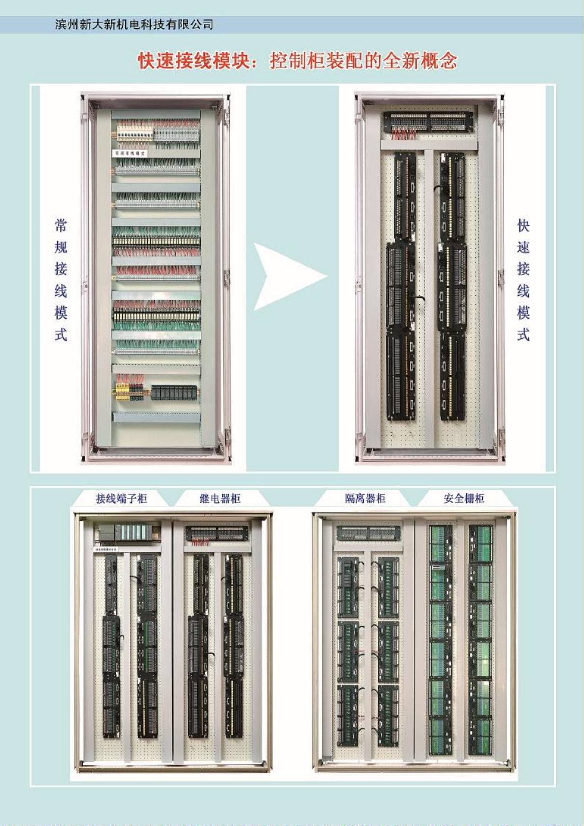
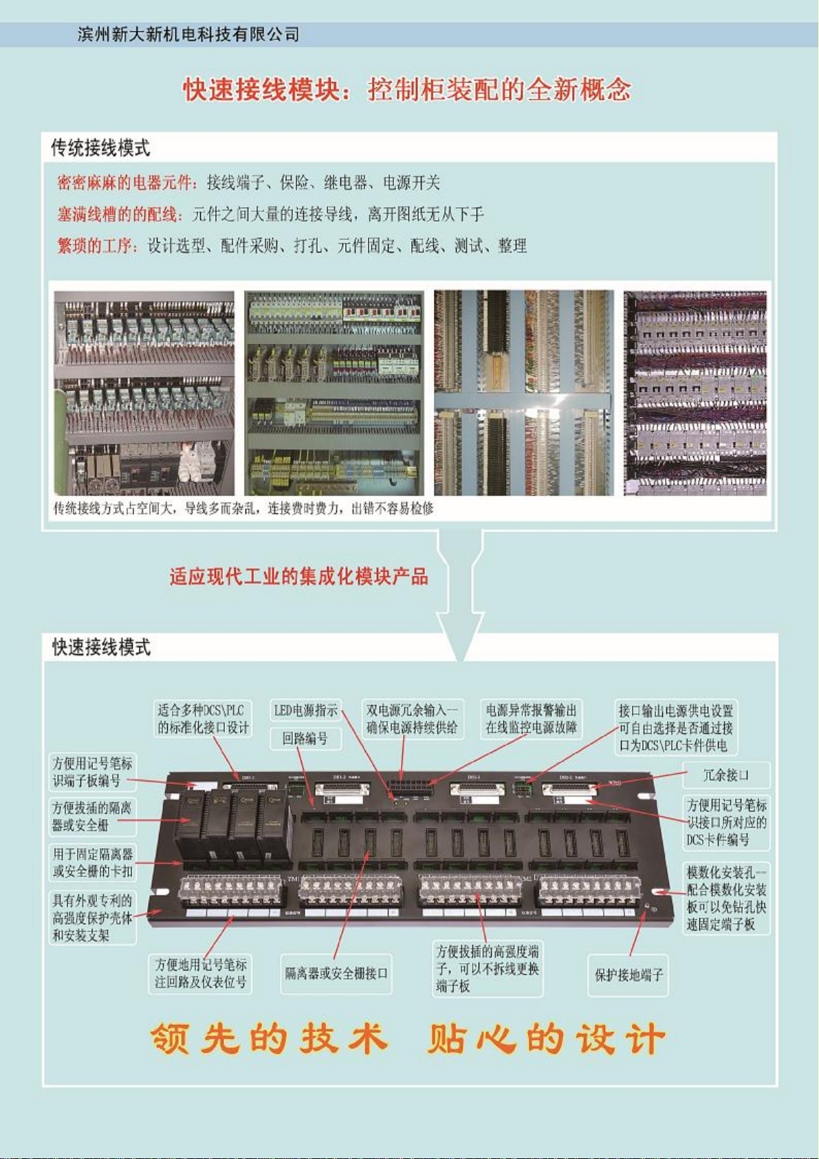
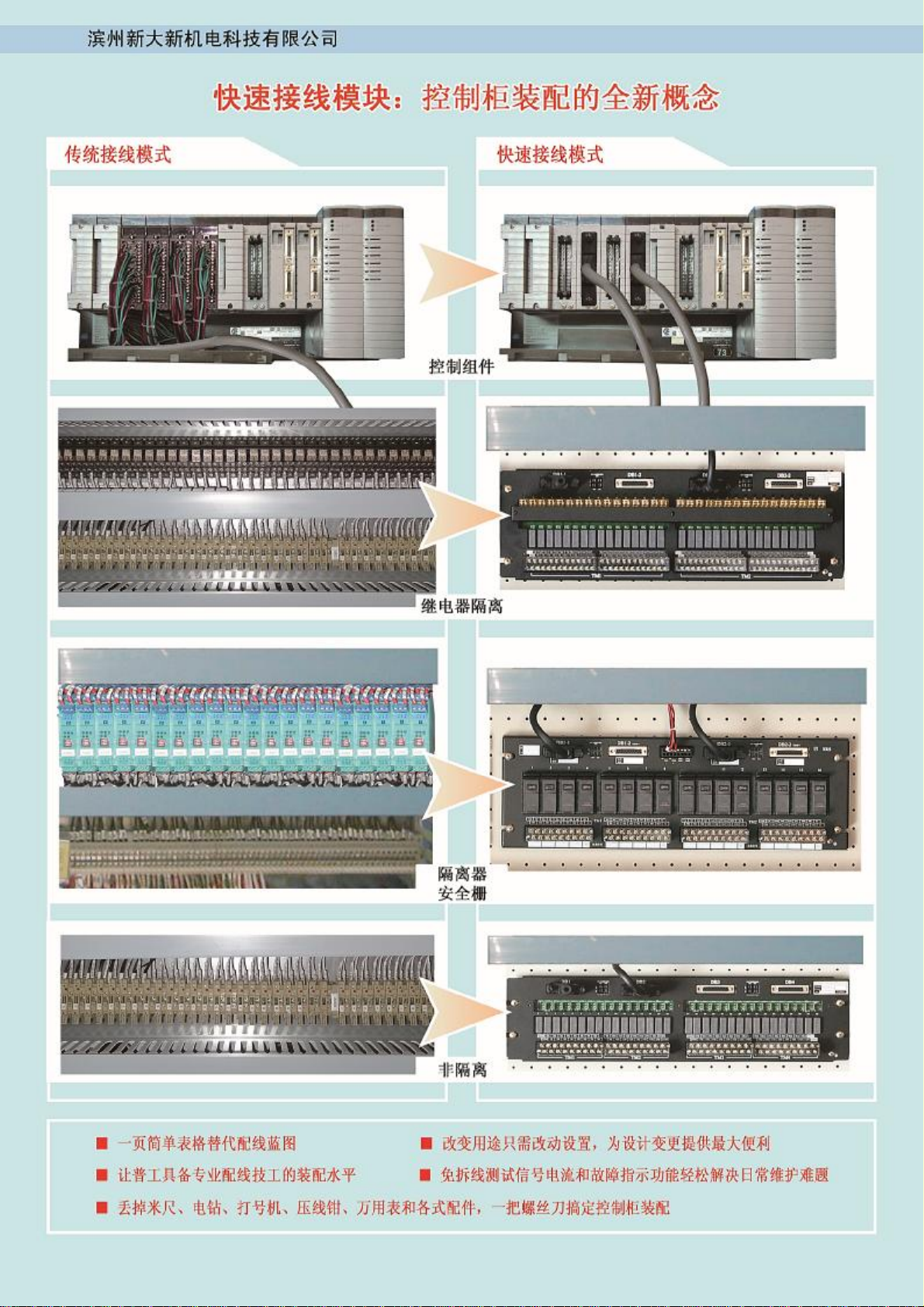
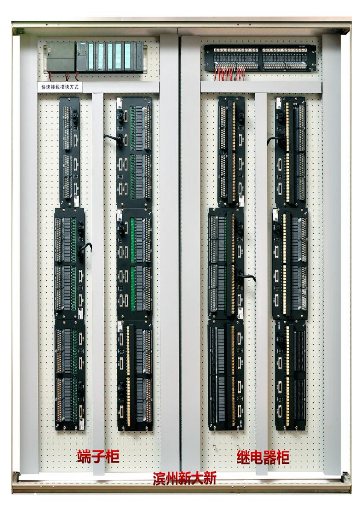
全球独家推出 全覆盖型省配线解决方案

http://www.bzxindaxin.com http://www.gk-world.com

http://www.bzxindaxin.com http://www.gk-world.com

http://www.bzxindaxin.com http://www.gk-world.com


INTRODUCTION
The following equipment is described in this documentation:
Controller Series ZETADYN 1DV
from Serial No. 39432xxxxx/xxxx
with control software as from version 3.02
It contains important information on
•Controller construction
•Connections
•Operation
•Control
•Commissioning
•Service
of the ZETADYN 1DV controller.
The Appendix contains suggested a wiring diagram and a setting data card.
The information contained within this documentation describes the features of our products
without guaranteeing the operation. We reserve the right to introduce changes without notice.
It is particularly important that you observe the following for your own safety:
Information on safe operation of the equipment.
Important information

Safety information
The electrical equipment and machines
described in this documentation are designed
for use in industrial heavy current systems. They
have parts which move or rotate and carry
dangerous voltages during operation. Therefore,
danger to health and property may be created if
the necessary guards of safety covers are
removed where this should not be done or if the
necessary maintenance work is neglected.
Consequently, those responsible for the safety
of the equipment must observe the following
rules:
- Only suitably qualified personnel* may be
entrusted with any work which needs to be
done on this equipment and machinery.
- Personnel working on this equipment and
machinery must have access to the operating
instructions and all product documentation
supplied and must observe the relevant
instructions contained therein.
- Unskilled personnel must not be allowed to
work on this equipment and machinery or in
the vicinity of it.
(*Definitions as in VDE 105 or IEC 364)
These safety instructions are not claimed to
cover all aspects of safety.
Notes
The information on processes and sections of
the circuitry contained in this documentation
must be regarded as such without further
implications. Their adaptation to other
applications must be investigated; ZIEHL-
ABEGG does not guarantee their suitability in
such circumstances.
The assemblies comprise components which
may be electro-statically endangered. The body
of the person touching them must first be
electrically neutralized, for example by first
touching a conductive, earthed object (e.g.
bright metal parts of an electrical cabinet or
earthing contact of a plug socket).
Written out as:
All settings at the unit are carried out with the
help of parameters grouped in menus.
Example: The running speed is determined
by the Parameter V_3 in the
TRAVELLING menu.
Written out as: /TRAVELLING/ V_3.
During electrical installation the following rules have to be observed:
VDE 0100 - Bestimmung für das Errichten von Starkstromanlagen mit Nennspannung bis 1000V
VDE 0113 (EN 60204) - Bestimmung für die elektrische Ausrüstung von Be- und Verarbeitungs-
maschinen.
VDE 0160 - Ausrüstung von Starkstromanlagen mit elektrischen Betriebsmitteln.
In special applications additional rules or directions must be observed.

ZETADYN 1DV System Description
Contents Page
0. Introduction
1. ZETADYN 1DV system information - Summary..............................................6
1.1 Applications ........................................................................................................6
1.2 Functions and features .......................................................................................6
1.3 Requirements......................................................................................................8
2. Mounting............................................................................................................9
2.1 Construction .......................................................................................................9
2.2 Installing the controller ........................................................................................ 9
2.3 Connecting and occupation of terminals ........................................................... 10
2.3.1 Mains .................................................................................................... 10
2.3.2 Motor ..................................................................................................... 11
2.3.3 Control inputs ........................................................................................ 12
2.3.4 Control outputs ...................................................................................... 13
3. Control and controller functions ...................................................................14
3.1 Controlling of ZETADYN 1DV ........................................................................... 15
3.2 Description of controller functions...................................................................... 16
3.2.1 Switching ON and OFF ......................................................................... 16
3.2.2 Start and accelaration ........................................................................... 16
3.2.3 Distance-controlled deceleration - Arch travel........................................17
3.2.4 Time based deceleration ....................................................................... 18
3.2.5 Distance-corrected deceleration ............................................................ 18
3.2.6 Normal slow down.................................................................................. 19
3.2.7 Quick stop.............................................................................................. 19
3.2.8 Readjustment ........................................................................................ 20
3.2.9 Direction reversal .................................................................................. 20
3.2.10 Short travel............................................................................................. 21
3.2.11 Troubles................................................................................................. 22
3.3 To ensure safe operation of the controller ........................................................ 23
4. Operation and settings...................................................................................24
4.1 Operating through keyboard and LCD display .................................................. 24
4.2 Remote operation with PC and ZETAMON software ........................................ 26
4.3 Summary of parameters ................................................................................... 27
4.3.1 The menu "Monitor" ..............................................................................28
4.3.2 The menu "Distances & Times" ............................................................. 29
4.3.3 The menu "Statistic" .............................................................................. 30
4.3.4 The menu "Travelling" ........................................................................... 31
4.3.5 The menu "Accelerating"........................................................................ 32
4.3.6 The menu "Decelerating" ....................................................................... 33
4.3.7 The menu "Controller" ........................................................................... 33
4.3.8 The menu "Operating" ........................................................................... 34
4.3.9 The menu "Installation".......................................................................... 35
4.3.10 The menu "Interfaces" ........................................................................... 37
4.3.11 The menu "ZA-Intern" ...........................................................................38

Contents Page
5. Commissioning...............................................................................................39
5.1 Requirements ................................................................................................... 39
5.2 Quick setup for mounting travels.......................................................................40
5.3 Setting of the "Switch off contacts" in the shaft.................................................. 41
5.4 Adjustment ........................................................................................................ 42
5.5 Final of setting up ............................................................................................. 44
6. Service .............................................................................................................45
6.1 Maintenance ..................................................................................................... 45
6.2 Troubleshooting ................................................................................................ 45
6.3 Repair................................................................................................................ 45
see appendix A9
APPENDIX:
A1 Technical data
A2 Denotation of controller types
A3 Dimension sheet
A4 Errorlist
A5 Error tracing plan
A6 Accessories
A7 Changes and new functions
A8 Schematic diagram
A9 HOTLINE-NOTIC
A10 Setting data card
Dieses Handbuch passt für folgende Modelle
6
Inhaltsverzeichnis