6mmFlyRC F-14 Tomcat Bedienungsanleitung

Instruction Manual
F-14 Tomcat
DISCLAIMER
6mmFlyRC guarantees our kits to be free from defects in both material and workmanship at the date of purchase. This warranty does
not cover any component parts damaged by use or modification. In no case shall 6mmFlyRC's liability exceed the original cost of the
purchased kit. Further, 6mmFlyRC reserves the right to change or modify this warranty without notice.
In that 6mmFlyRC has no control over the final assembly or material used for final assembly, no liability shall be assumed nor
accepted for any damage resulting from the use by the user of the final user-assembled product. By the act of using the user-
assembled product, the user accepts all resulting liability.
If the buyer is not prepared to accept the liability associated with the use of this product, the buyer is advised to return this kit
immediately in new and unused condition to 6mmFlyRC for a full refund.
While this kit has been flight tested for normal use, if the plane will be used for extremely high stress flying, such as racing, the
modeler is responsible for taking steps to reinforce the high stress points.
*Special thanks to Steve Shumate, who not only has provided the instructions for the T-38, F-14, F-15, F-18, and Saab Gripen, but has provided
much needed support to 6mmFlyRC. Without Steve, our job would be much harder.

Page 2
This model was designed to be built from either BlueCore fan-fold foam or
6 mm Depron foam. If using BlueCore, note you’ll need to peel the film
backing off the fuselage exterior parts to allow sanding the fuselage corners
to shape. Leave the film on the wing and empennage parts since it adds
strength, durability, and smoothness.
Note this model is best built using the following types of adhesives:
•Epoxy (both 5 minute and 30 minute)
•Odorless CA (with accelerator)
•Contact glue such as UHU Creativ for Styrofoam
•3M 77 spray adhesive
ProBond can also be used in place of epoxy. It is lighter than epoxy but
takes much longer to cure (overnight). I have personally found UHU Creativ
for Styrofoam (picture at left) to be the best glue for the majority of assembly,
since it’s easy to use, dries fast (less than 10 minutes), and is quite strong.
Begin by cutting out all of the paper parts templates with scissors, trimming
them to within approximately 1/8” of the lines. Then test fit all of the
templates onto the foam sheet, trying to minimize wasted foam as much as
possible. Once you’re satisfied with the arrangement, remove each template
individually and spray the back of the template LIGHTLY with 3M 77 spray
adhesive. Then replace the template onto the same spot on the foam sheet.
Repeat for every template.
After all the templates are tacked onto the foam, cut out all the pieces by
cutting on the lines with a SHARP hobby knife. When done, peel the paper
templates off of each piece and discard.

Page 3
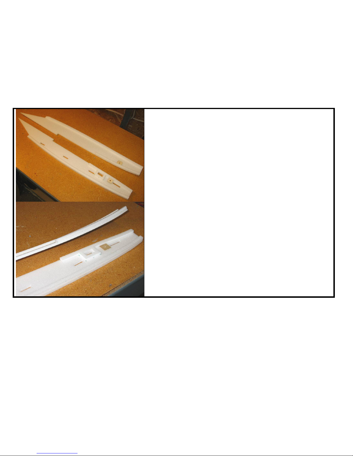
1. Begin assembly with the forward fuselage. Lay the two fuselage sides
down flat on the work bench and glue the foam doublers to the locations
shown on the parts templates. Be sure to make two mirror image parts—a
left side and a right side.
Use a heat gun to gently heat the foam and form the curves in these
pieces. Hold each piece up next to the piece it mates to to judge the
curvature.
After the glue has dried, glue the three fuselage bulkheads to one of the
fuselage sides at the locations shown, making sure they are perpendicular.
2. Next glue the two fuselage sides together. Set the fuselage sides upright
and flat on the workbench, apply glue to the edge of the bulkheads, and
push the sides together.
After the glue has dried, glue this assembly to the fuselage bottom piece
as shown.
Glue the two forward fuselage top pieces in (forward of the canopy).

Page 4
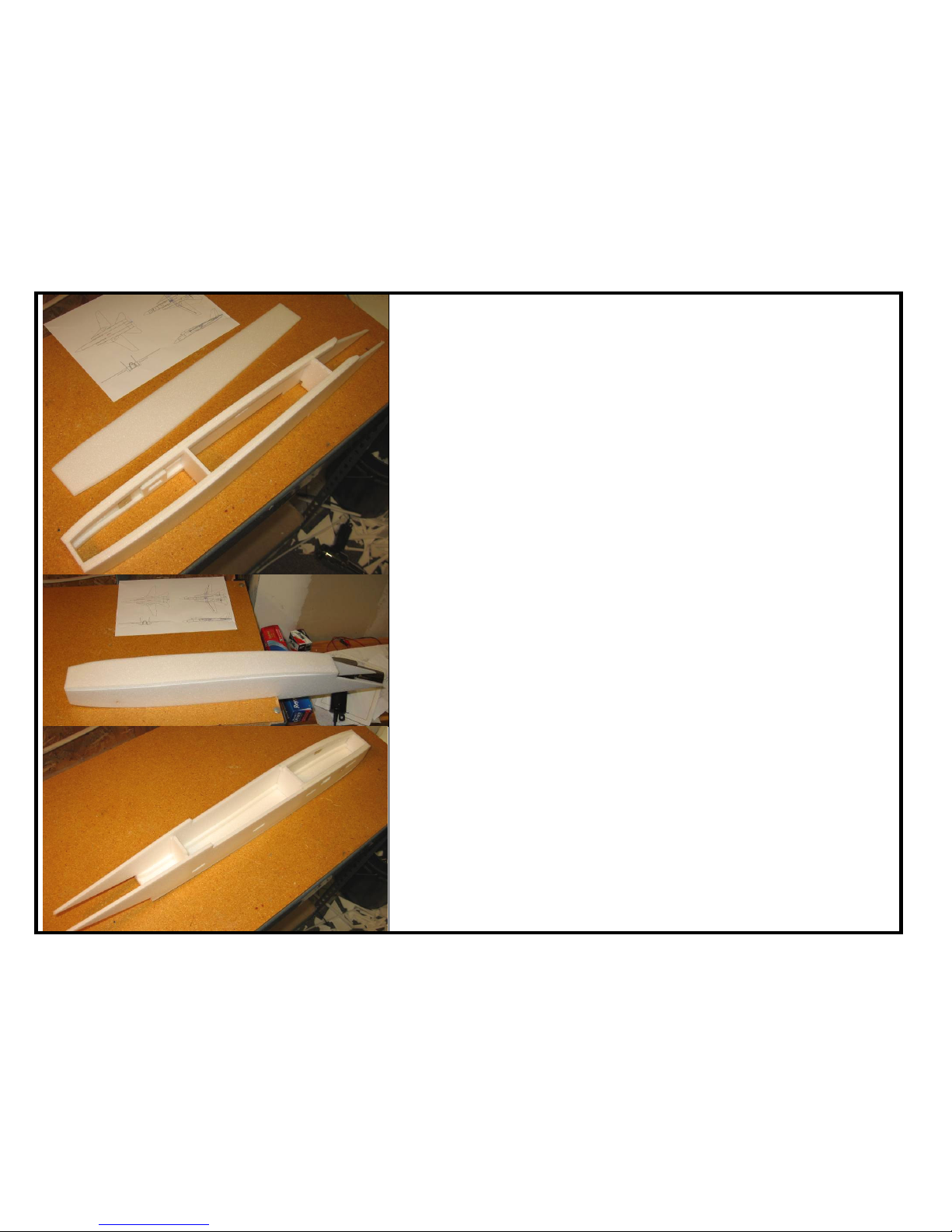
3. Laminate the nose cone pieces together using 3M 77 spray adhesive.
Then glue the assembled nosecone block to the forward fuselage as
shown (5 minute epoxy recommended).
Once the glue has dried, carve the nose cone to shape. Start by tracing
the top view template on the top of the block and cutting the block to that
outline. Begin with coarse sandpaper (60 grit) to rough out the basic
shape, then move to progressively finer sandpaper (first 150, then 220 grit)
to do the final shaping.
Make the canopy using the same procedure. Note the canopy has two
smaller sill pieces that glue on to each side of the canopy to form the lower
sill.
Page 5
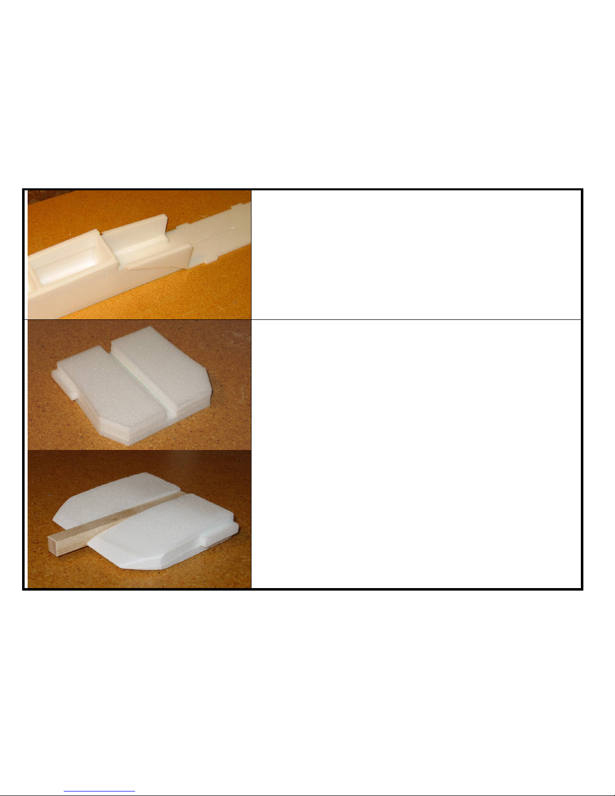
4. Begin assembly of the inlets. Be sure to make two mirror-image inlets!
First glue the small plywood stabilizer support squares to each side in the
locations shown on the plans, and then drill the 3/16” holes for the stab
pivots. Then glue the foam support strips as shown to both the inboard
and outboard inlet sides. Glue the taileron servo doubler to the inboard
inlet side.
Use a heat gun to gently form the required curves in these pieces. Hold
each piece next to the inlet bottom piece to judge the curvature required.
Page 6
5. Tack glue the three temporary inlet bulkheads to one side (these will be
removed later), and then tack glue the two inlet sides together.
Next glue the inlet bottom piece on. To make sure the inlets are
assembled perfectly square, hook the sides over a bench as shown and
hold the inlets flat against the bench as the glue dries.
After the glue has dried, sand the corners of the inlets to a well-rounded
shape.
Page 7
6. Glue the inlet diverters to the fuselage sides. Note the bottom of the
diverter butts up against the step in the fuselage bottom piece.
7. Laminate the five motor mount pieces together using 3M 77. Note the
tabbed piece goes in the middle. Then sand the assembly to a tapered
shape as shown.
Glue in the hardwood motor mount using 5 minute epoxy.
Page 8
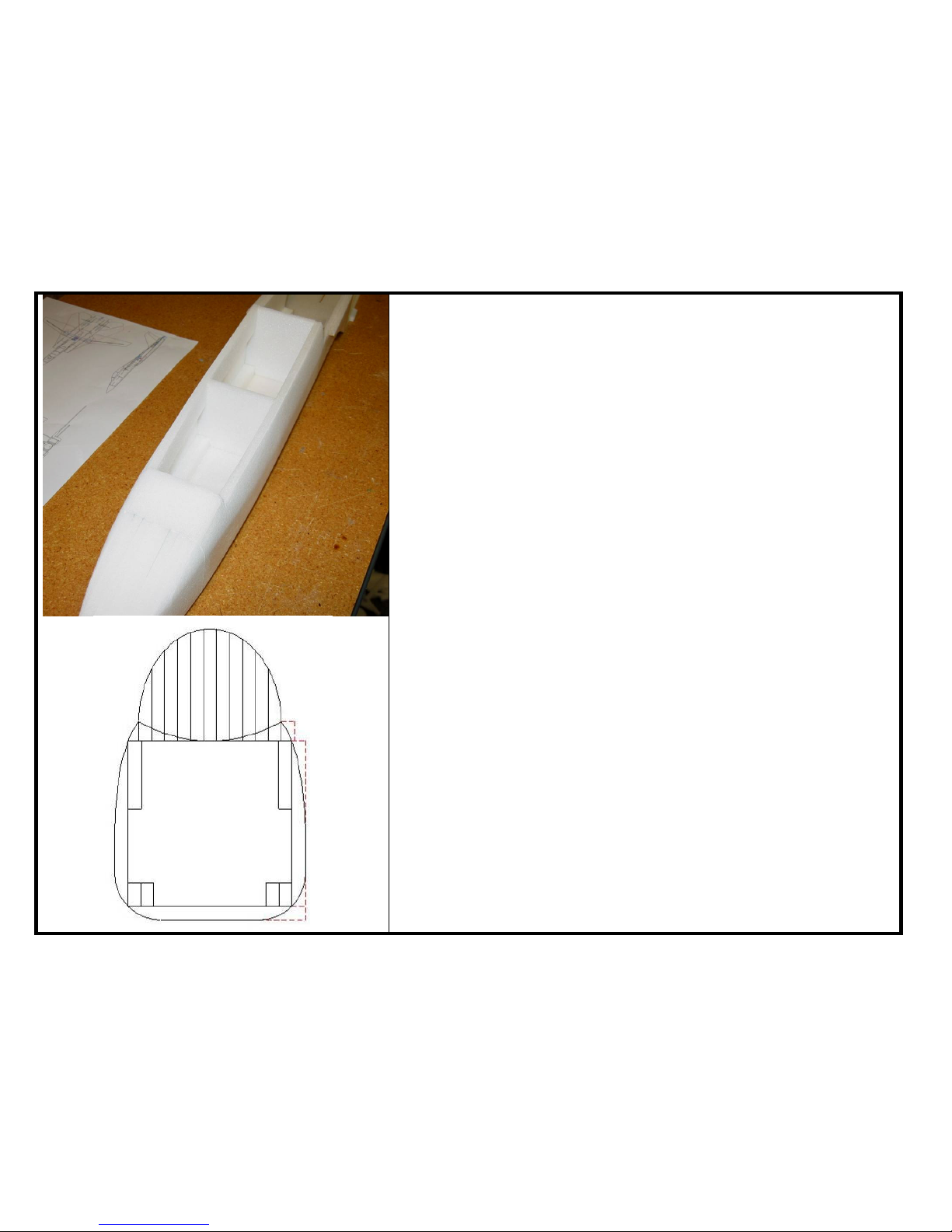
8. Sand the forward fuselage to the contours shown. It’s important to do this
now before you glue the inlets to the side of the fuselage, since the inlets
will block access to the aft part of the fuselage. Sand the bottom edges to
a circular shape, and then sand the top edges down to the feathered
shape shown on the diagram at left. Note how the tops of the fuselage
sides blend into the canopy sill.
Page 9
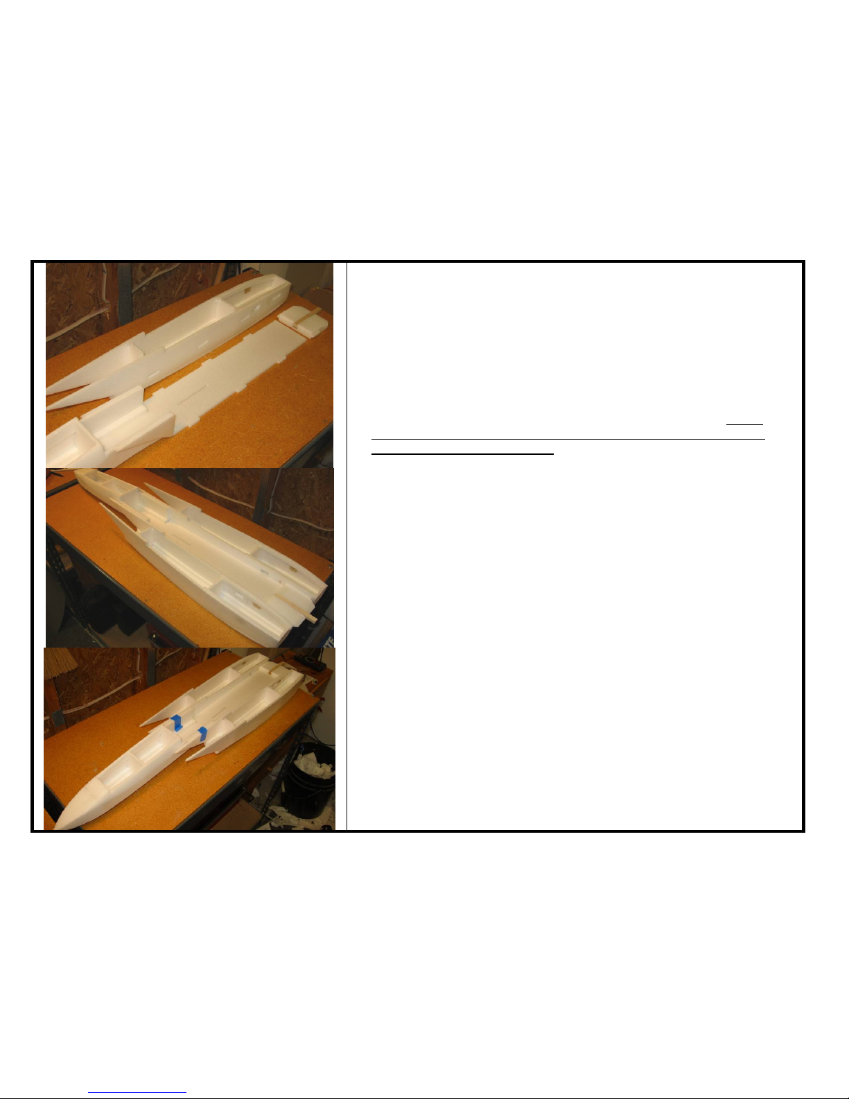
9. Next glue the inlets to each side of the fuselage. Note that the tabs on the
fuselage bottom piece slide into corresponding slots in the inlet sides,
which automatically ensures proper alignment. But you’ll need to make
sure the inboard forward top edges of the inlets are flush with the top of
the aft fuselage (the area held together with blue tape in the bottom picture
at left). Note that the motor mount also has tabs and slots to ensure
proper alignment as well. 15 minute epoxy is highly recommended for this
step, both for strength and to give you time to get everything aligned
before the glue sets. Set the fuselage upside down on the workbench
(hooked over an edge with the inlet tops sitting flat against the bench) as
the glue cures to ensure this assembly is perfectly flat on top. This is
important because the wing spar box will span across the top and the
wings will fold up on top as well.
After the glue has cured, remove all of the temporary bulkheads inside the
inlets.

Page 10
10.Now we’ll build the wing sweep mechanism. Begin by cutting out all the
plywood parts using a similar procedure as the foam parts—just tack glue
the paper templates to the wood using 3M 77 spray and then cut the parts
out with a sharp hobby knife (that’s one of the beauties of lite-ply—it can
be cut quickly with a knife!).
When done, you should have all of the parts shown in the bottom picture at
left.
11.Glue the doublers to both ends of the spar box top and bottom pieces.
Laminate the two spacer pieces and glue them in place on top of the
doublers on one side. Then glue the balsa shear webs in place on the
same side. Medium viscosity CA is recommended for all of these joints.
Next laminate the two swing arm pieces together with CA. Be sure to
make two mirror-image parts—the piece with the control arm goes on
bottom for each side.
Inhaltsverzeichnis
Andere 6mmFlyRC Spielzeug Handbücher


