AKCP sensorProbe8 Bedienungsanleitung

www.AKCP.com
sensorProbe2 /
sensorProbe8/
sensorProbe8-X20
User Manual
Help Version updated till firmware 413
Copyright © 2009, AKCP Co., Ltd..

SP2/SP8/SP8-X20 Manual
Updated until firmware 413 - 2 -
1) Introduction
1. What is sensorProbe?
2. What’s the difference between SP2 and SP8?
3. What’s the difference between SP8 and SP8-X20?
4. How to use this manual
5. sensorProbe2
6. sensorProbe8
7. sensorProbe8-X20
8. sensorProbe8-X20 20 Extra Dry Contact Inputs
2) Installation
1. Assigning an IP address
2. Testing your new IP address
3. Upgrading the firmware
3) Setting up a sensor
1. Basic Setup
4) Notifications
1. Setting up a trap
2. Setting up Email notifications
5) System Settings
1. Network Settings
2. System tab
6) Making your unit visible to the internet
7) Quick Facts and FAQ

SP2/SP8/SP8-X20 Manual
Updated until firmware 413 - 3 -
1) Introduction
1. What is sensorProbe?
The sensorProbe2, sensorProbe8 and sensorProbe8-X20 (SP2/SP8/SP8-X20) are
intelligent devices for monitoring environmental variables, power, physical threats and
security. The units are IP based and include a web interface for configuration. Included in
this is a TCP/IP stack, Web server, full SNMP and E-mail support.
Any of our AKCP intelligent sensors can be connected via the RJ45 connections
(excluding our daisyTemp, 8 port sensor controlled relay, thermocouple or PMS sensors),
or you can add dry contact connection for monitoring UPS, security systems and air
conditioning status.
2. What’s the difference between the SP2 and the SP8?
The SP2 is a small unit with facility for 2 RJ45 sensor inputs. The SP8 is a larger unit with
the facility for up to 8 RJ45 inputs.
3. What’s the difference between the SP8 and the SP8-X20?
The sensorProbe8-X20 has the 8 RJ-45 intelligent sensor ports AND has 20 extra dry
contact inputs, where the sensorProbe8 only has the 8 RJ-45 sensor ports. More on
these extra dry contacts in topic #8 in this section below.
4. How to use this manual
This manual aims to provide the user with a step by step guide on how to get your unit
set up and functioning. It will introduce the primary features of the unit by way of tutorials.
You can either go through the whole procedure from start to finish, or, if you wish, use
each tutorial as a standalone lesson. The start of each lesson gives an “entry point
profile” which details how to get to the start point of the lesson and assumes previous
knowledge through completion of previous tutorials.
Quick Tip:
Throughout this manual you will find “Quick Tips” in each section that will relate to the
information you are reviewing. Also, in section #7 you find a “Quick Facts” and “FAQ”
section that covers common questions and problems you may encounter. If however you
need any further assistance please don’t hesitate to contact our support team on
support@akcp.com

SP2/SP8/SP8-X20 Manual
Updated until firmware 413 - 4 -
5. sensorProbe2
6. sensorProbe8

SP2/SP8/SP8-X20 Manual
Updated until firmware 413 - 5 -
7. sensorProbe8-X20
8. sensorProbe8-X20 20 Extra Dry Contact Inputs
The 20 extra dry contact inputs on for example, the sensorProbe, (or securityProbe
X20/X60) can be configured as inputs only up to 5 Volts in normal operation. In opto-
isolation mode they can input up to 30 Volts DC. This will protect these inputs and the
unit from high voltages and spikes.
Opto-isolators provide complete electrical separation between the securityProbe and the
dry contact. The base units are therefore protected against possible large voltage spikes
caused by lightning for example.
The figure below shows the JUMPERS (on the dry contact board) set up to provide opto-
isolators support. Opto-isolators provide complete electrical separation between the
sensorProbe and the dry contact.
The OID for the extra dry contact inputs is:- .1.3.6.1.4.1.3854.1.2.2.1.18.1.3.<port>

SP2/SP8/SP8-X20 Manual
Updated until firmware 413 - 6 -
Extra dry contact input practical applications:
The extra dry contact inputs can be used to monitor many types of equipment, for example, you
can run the connection from warning lights on alarm panels to the dry contact inputs, so that
when the warning light on the alarm panel is activated, the dry contact is triggered in the units
web interface, thus allowing you to send notifications via emails or SNMP traps.
2) Installation
1. Assigning an IP address
These units are plug and play devices that will easily connect to your existing network
setup. Every unit ships with a default IP address. This is 192.168.0.100. The first steps
you will need to undertake to install your unit will be to assign it an IP address to match
your current network configuration. Before starting this, ensure you have the following
items:-
1. RJ45 CAT5 crossover cable with RJ45 male connection
2. A PC with Ethernet card or LAN socket.
3. Power socket for the unit to connect to
a) Connect the unit via the CAT5 crossover cable to the Ethernet / LAN port on your
computer.
b) Open your web browser and go to the default IP address http://192.168.0.100
SP2/SP8/SP8-X20 Manual
Updated until firmware 413 - 7 -
In some cases your computer might not be able to connect to this default IP address.
In this situation you need to set up your computers routing table to allow access to
this. See here for this process.
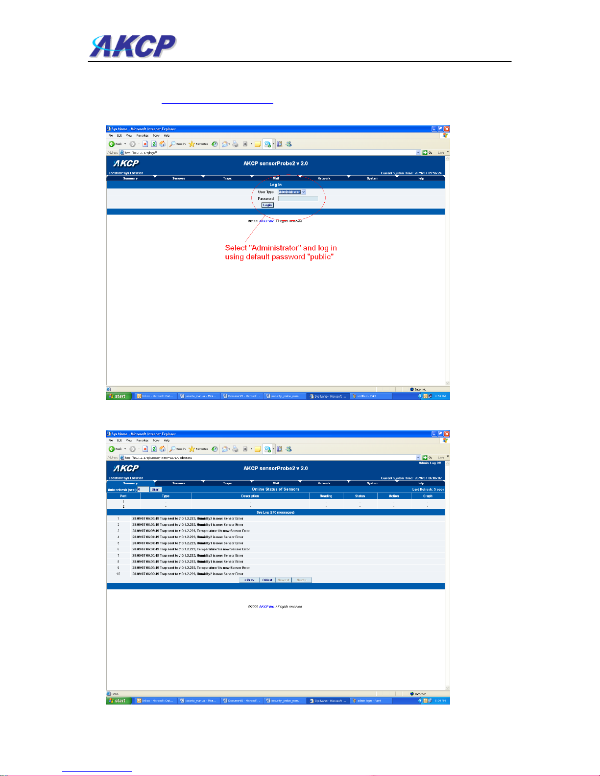
c) You will now be presented with the following login screen.
d) After logging in you will be taken to the main summary page.

SP2/SP8/SP8-X20 Manual
Updated until firmware 413 - 8 -
e) From summary page select the “Network” tab. After inputting your new IP address click
“save”
2. Testing your new IP address
We now need to test that your new IP address has been assigned successfully. We will do this
via the “ping” command.
1. Click start/run……

SP2/SP8/SP8-X20 Manual
Updated until firmware 413 - 9 -
2) You will now get an MS DOS command prompt which shows the ping results. If this is
unsuccessful you will receive a “request timed out” message.
Having connection problems? Please note:
The units default connection speed is 10MB w/Half Duplex, so if you are having trouble
connecting to the unit then you do have the option to set the unit to full duplex mode by using the
follows SNMP set command
snmpset -v1 -c public 192.168.0.100 .1.3.6.1.4.1.3854.1.2.2.1.72.0 s "1yyy"
To set back to halfduplex -->
snmpset -v1 -c public 192.168.0.100 .1.3.6.1.4.1.3854.1.2.2.1.72.0 s "0yyy"
where 'public' is admin password. Where '192.168.0.100' is the sensorProbe’s IP address. The
duplex mode is shown on Network Settings page.
Quick Tip:
If you’re still having trouble connecting to your sensorProbe, or opening your unit’s web interface,
please see the FAQ in section #7 at the end of the manual for more help.
SP2/SP8/SP8-X20 Manual
Updated until firmware 413 - 10 -
3. Upgrading the firmware
As we are constantly releasing new firmware with added capabilities it is recommended you
upgrade to the latest firmware. To do this you need to go to our website
http://www.akcp.com/company/firmwareupdate.htm and log in using your MAC address. This can
be found on a sticker on the base of your unit.
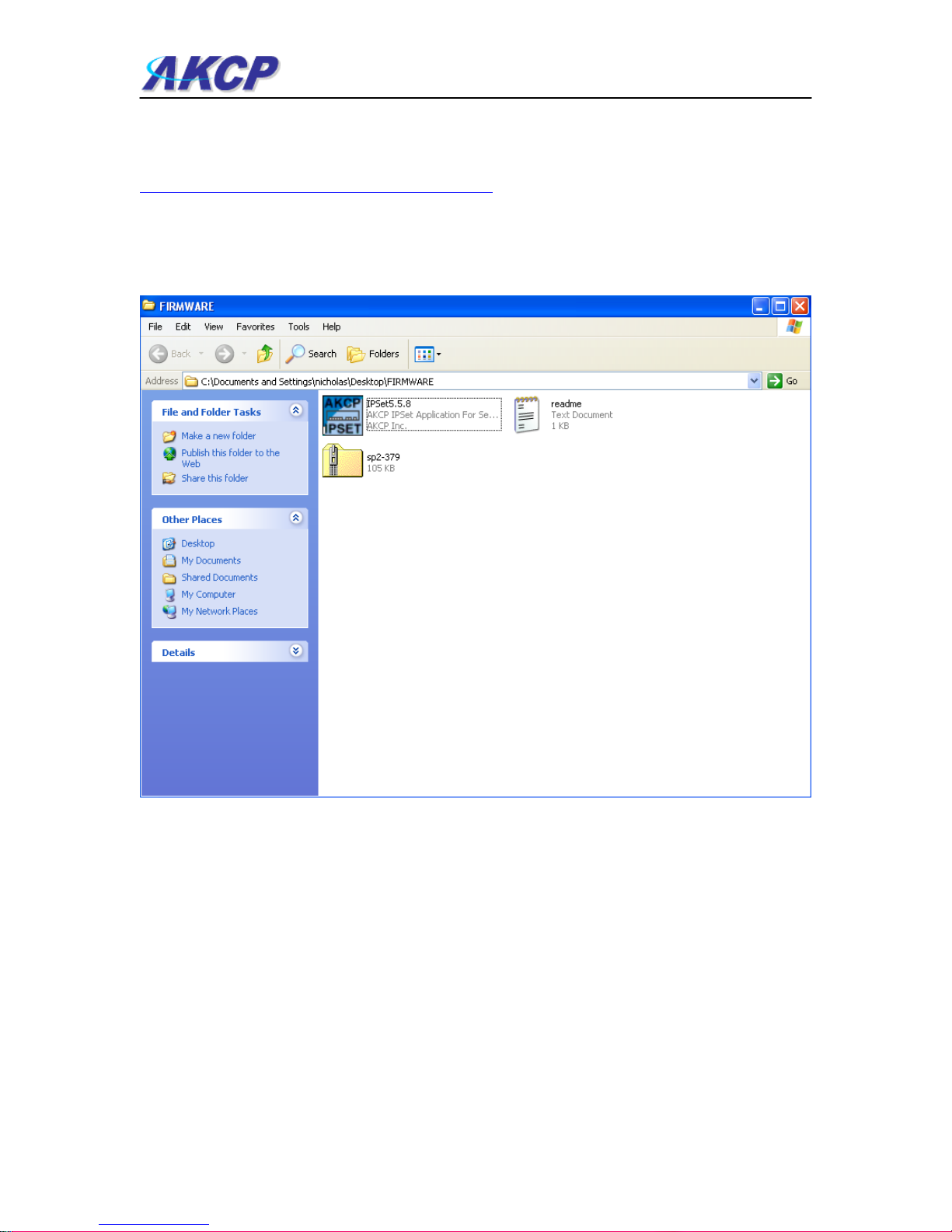
1) When you download your firmware it will come in a zip package. Extract this to your desktop
into a folder named firmware. When you open this folder you will see something like the
following:-
You can see one of these files is a program named IPSet. This utility will upload the firmware to
your unit. Double click the program to boot it.
Dieses Handbuch passt für folgende Modelle
4
Inhaltsverzeichnis
Andere AKCP Messgerät Handbücher

AKCP
AKCP FreeRADIUS SP+ Bedienungsanleitung

AKCP
AKCP SPX+ Referenzhandbuch

AKCP
AKCP ILPM Bedienungsanleitung

AKCP
AKCP SP1+ Gebrauchsanweisung

AKCP
AKCP PMS120-CT50 Bedienungsanleitung

AKCP
AKCP SensorProbe2 PLUS Referenzhandbuch

AKCP
AKCP SP1+ Bedienungsanleitung

AKCP
AKCP sensorProbe2 Bedienungsanleitung

AKCP
AKCP Inline Power Meter AC Bedienungsanleitung


