
ARAG Orion 2 46211A Series Kurzanleitung

46211AXXXXX
46221AXXXXX
ELECTROMAGNETIC FLOWMETER
INSTALLATION, USE AND MAINTENANCE

LEGEND SYMBOLS
=Generic danger
=Warning
CONTENTS
Legend symbols...................................................................................................................................................................................... 2
1 Product description ............................................................................................................................................................................... 3
1.1 Intended use................................................................................................................................................................................... 3
2 Installation............................................................................................................................................................................................... 3
2.1 Dimensions (mm)......................................................................................................................................................................... 4-6
2.2 Assembly ........................................................................................................................................................................................ 7
2.3 Electric connections........................................................................................................................................................................ 8
2.4 Hydraulic connections..................................................................................................................................................................... 8
2.5 Hydraulic connections for control units ........................................................................................................................................... 9
3 Preliminary setup for use..................................................................................................................................................................... 10
4 Use ......................................................................................................................................................................................................... 10
5 Maintenance ...........................................................................................................................................................................................11
5.1 Troubleshooting .............................................................................................................................................................................11
5.2 Technical data........................................................................................................................................................................... 11- 12
6 Guarantee terms.................................................................................................................................................................................... 13
7 Disposal at the end of service ............................................................................................................................................................. 13
This manual is an integral part of the equipment to which it refers and must accompany the equipment in case of sale or
change of ownership. Keep it for future reference; ARAG reserves the right to modify the specications and instructions
regarding the product at any time and without prior notice.
3
1 PRODUCT DESCRIPTION
The Orion 2 electromagnetic owmeter is a device that enables measurement of the quantity of liquid passing through it.
Using a principle of electromagnetic measurement (there are no moving mechanical parts inside it), the owmeter outputs a signal to the computer
proportional to the liquid ow that goes through it; Orion 2displays the owrate calculated according to the data received from the owmeter and the
value of the owmeter constant previously set.
1.1 Intended use
This device is designed to work on agricultural machinery for crop spraying applications.
The machine is designed and built in compliance with EN ISO 14982 standard (Electromagnetic compatibility - Forestry and
farming machines), harmonized with 2004/108/EC Directive.
The owmeter must not be used to measure the passage of hydrocarbons, ammable, explosive or toxic liquids. The owmeter is
not suitable for contact with liquids for human consumption. Use for sales transactions is not allowed.
2 INSTALLATION
Install the owmeter at least 20 cm from the elements that could cause turbulence inside the tubes (valves, bends, constrictions, etc.).
The owmeter can be installed in a horizontal or vertical position.
CAUTION:
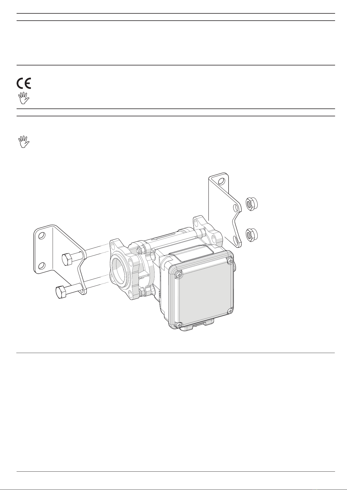
For proper sealing of the owmeter, use ARAG assembly kit ONLY (Ref. ARAG General catalogue - Accessories for series 463/473
modular valves).
ARAG is not liable for damage to the system, persons, animals or things caused by the use of material other than specied.
CONTINUES
Fig. 1
4
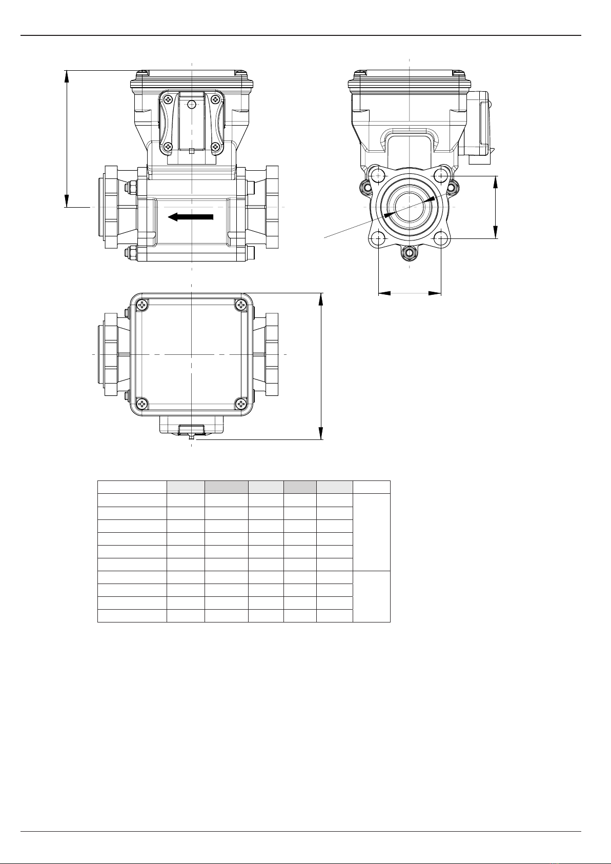
2.1 Dimensions (mm)
H
DN
X
X
A
CODE DN A H L X ange
46211AG0000 4 96 90 114 41
463
863
46211A00000 5 96 90 114 41
46211A10000 7 96 90 114 41
46211A20000 10 96 90 114 41
46211A30000 14 96 90 114 41
46211A40000 18,5 96 90 114 41
46221A40000 18,5 96 90 114 45
473
873
46221A50000 28 96 90 114 45
46221A60000 28 96 90 114 45
46221A70000 28 96 90 114 45
Fi g . 2
Tab. 1

5
Dimensions (mm)
DN
A
L
F
H
CODE DN F A H L
46211AG1313 4 G 3/4 96 90 185
46211AG3333 4 G 3/4 96 90 184
46211A01313 5 G 3/4 96 90 185
46211A03333 5 G 3/4 96 90 184
46211A11313 7 G 3/4 96 90 185
46211A13333 7 G 3/4 96 90 184
46211A21313 10 G 3/4 96 90 185
46211A23333 10 G 3/4 96 90 184
46211A31414 14 G 1 96 90 185
46211A33434 14 G 1 96 90 184
46211A41414 18,5 G 1 96 90 185
46211A43434 18,5 G 1 96 90 184
46211A41515 18,5 G 1 1/4 96 90 189
46221A51515 28 G 1 1/4 96 90 191
46221A51616 28 G 1 1/2 96 90 199
46221A61616 28 G 1 1/2 96 90 199
46221A61717 28 G 2 96 90 234
46221A71717 28 G 2 96 90 234
Fi g . 3
Tab. 2

6
Dimensions (mm)
DN
H
L
T
A
T
CODE DN T A H L
46211A3A5B5 14 T5 96 90 192
46211A4A5B5 18,5 T5 96 90 192
Fig. 4
Tab. 3
7
2.2 Assembly
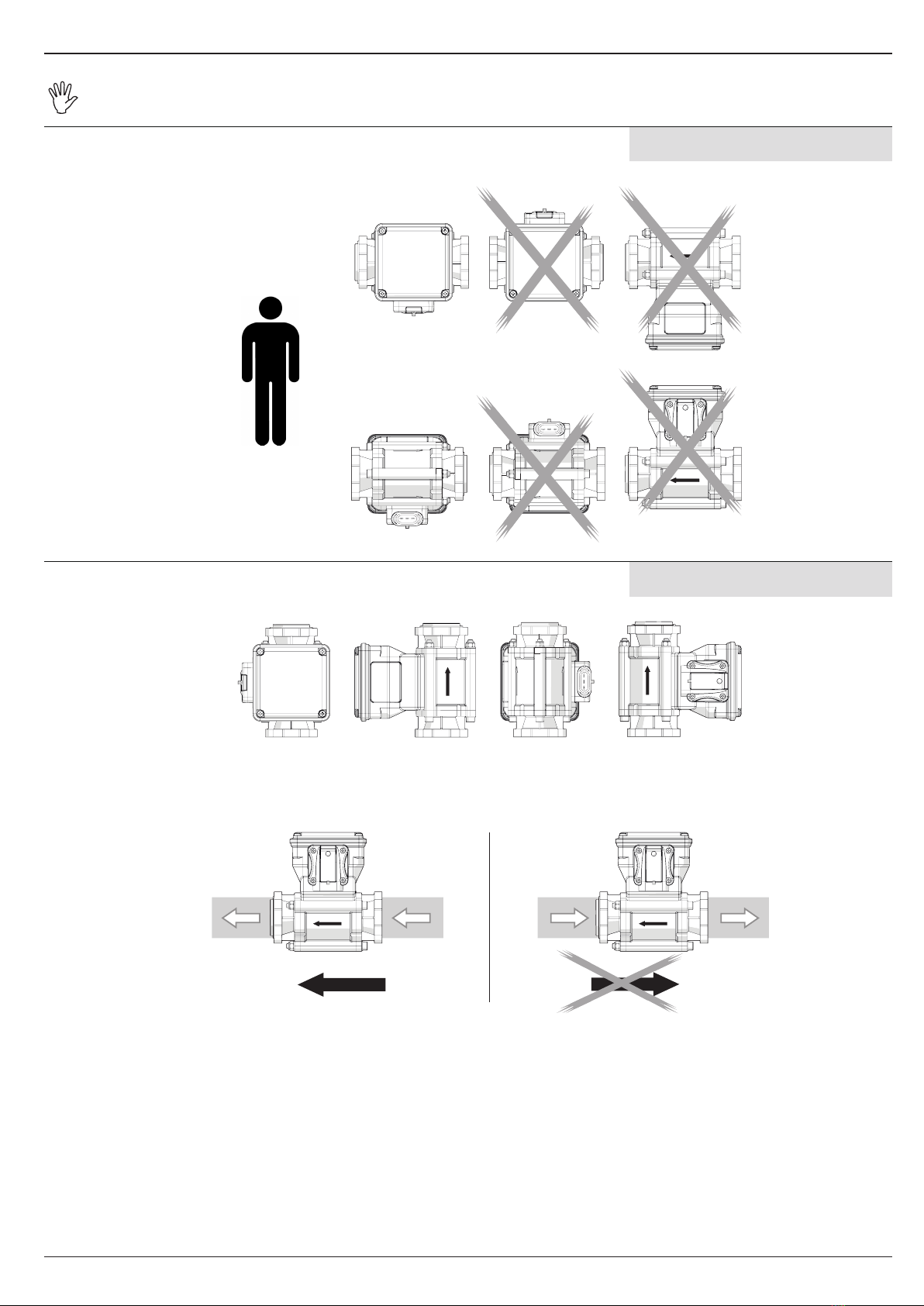
To ensure trouble-free operation, comply with the indicated installation layout (Fig. 5a and Fig. 5b).
The connector must NEVER be positioned upwards.
OK
OK
- Comply with the correct uid inlet-outlet direction, as indicated by the arrow printed on the owmeter body (Fig. 6).
INOUT IN OUT
Use inlet and outlet pipes of the same diameter as the internal passages of the owmeter; for any reference, see tables 7a-7b-7c
(Chap. 5 - Technical data).
HORIZONTAL ASSEMBLY
VERTICAL ASSEMBLY
Fig. 5a
Fig. 5b
Fig. 6

8
2.3 Electric connections
The Orion 2owmeter has been designed to be connected to ARAG devices (computers, screens, displays) but can also be connected to equipment
made by other manufacturers as long as they are designed for owmeters of this typology.
ARAG is not liable for damage to the system, persons, animals or things caused by incorrect or inadequate installation of the
owmeter. In the event of damage to the owmeter, caused by incorrect or unsuitable assembly, any form of guarantee is auto-
matically rendered null and void.
Color Position Connection
Black 1GND
Red 2+12 VDC
Green 3Signal
(square wave)
2.4 Hydraulic connections
For connection to the system, use appropriate ttings (Ref. ARAG General catalogue).
Avoid bends and constrictions before connections and on tubes.
Regarding connections, use tubes and ttings properly sized for the operating pressure of the system.
The tightening of hose tails should be made with special metal clamps ensuring perfect sealing even at high pressures.
The connection by means of threaded ttings should be done taking operating pressure into account.
CAUTION: For the implementation on already operating systems it is necessary to follow all safety rules described herein.
System assembly and start-up must be carried out by expert personnel according to the safety rules so as to ensure the same
safety level of the system the owmeter is going to be installed in.
Tab. 4

9
2.5 Hydraulic connections for control units
The Orion 2 owmeters to be integrated in the control units are available with both anged 863/873 (in previous 463/473 series) and T5 fork coupling
connectors.
If you need to integrate the owmeter in an existing tie rod control unit previously congured without a owmeter, remember to order new tie-rods
in order to reconstruct the unit correctly after the owmeter has been incorporated (Ref. ARAG general catalog, control unit section, assembly kit).
ONLY use ARAG tie-rods. If other tie-rods are used, the warranty is automatically void.
Flowmeters with fork coupling do not need other accessories and can be directly inserted in the existing control unit provided it already comes with
T5 fork coupling.
CAUTION: BEFORE INCORPORATING THE FLOWMETER TO AN EXISTING CONTROL UNIT, MAKE SURE THAT THE OPERATING
PRESSURE IS SUITED FOR THAT SPECIFIC CONTROL UNIT.
FLOWMETERS WITH T5 FORK COUPLING CAN WITHSTAND A MAXIMUM PRESSURE OF 20 BAR.
ARAG is not liable for damages to the equipment, persons, animals or objects caused by failure to observe the above instructions.
Remember to correctly position seals and O-Rings in the coupling seats.
Note: usually, in standard control units, the owmeter is inserted between the control valve and the section valves unit (Fig. 8a-8b).
This does not prevent the assembly of the owmeter in any other part of the control unit, however, keep in mind that if the owmeter is positioned in
different points the values may differ depending on the connected components.
Filtering the liquid is recommended.
In order to obtain a correct reading, contact a dealer or installer that can give you advice on how to correctly position the
owmeter inside the control unit.
FLANGED CONNECTOR FORK COUPLING
Incorporating anged connector
Incorporating fork coupling
Fig. 8a
Fig. 8b
10
3 PRELIMINARY SETUP FOR USE
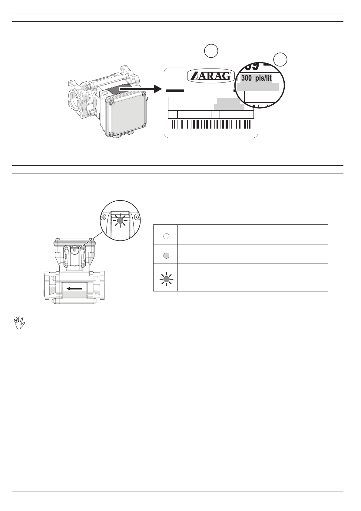
Set owmeter constant (B, Fig. 9): on the computer connected to Orion 2owmeter: refer to the label on the body (A, Fig. 9) and tables 7a-7b-7c -
Chap. 5 "Technical data".
Rubiera (RE)
MADE
IN
ITALY
H195099
s/n :
10 ÷ 200 lit/min 300 pls/lit
2.6 ÷ 53 GPM l 1135 pls/GAL
20 bar 290 psi 40 bar 580 psi
QC PASSED 12VDC 300mA
}
A
40 bar 580
B
1135 pls/GAL
For further information regarding how to set the constant, consult the use and maintenance manual of the computer being used.
4 USE
When using the system, the owmeter sends impulses to the computer, which, according to the constant value previously set, indicates the instant ow.
A LED in the connector slot indicates the status of the device (Fig. 10):
Orion 2 owmeter can only detect conductive uids with a conductivity equal to 50 μS/cm (Rif. Tab. 5.2 - Chap. 5).
- Do not aim pressurised water onto the equipment.
- Respect the device’s rated power requirement (12 Vdc).
- If arc welding is required, ensure that owmeter power is off and disconnect the power cables, if necessary.
- Use the owmeter only within the ow limits given in the “Technical data” table. Outside these limits, the owmeter could give incorrect
data and therefore lead the operator or the automatic system to make errors.
ARAG cannot be held responsible for damage caused to persons, animals or things by incorrect or unsuitable use of the owmeter or its parts.
Fig. 9
Fig. 10
LED OFF:
the device is not powered.
LED ON NOT FLASHING with low light intensity:
the device is powered but it does not detect liquid passage.
LED ON FLASHING with high light intensity:
the device is powered and it detects liquid passage.
La frequenza dell'intermittenza è proporzionale alla portata.
Dieses Handbuch passt für folgende Modelle
31
Inhaltsverzeichnis
Andere ARAG Messgerät Handbücher

ARAG
ARAG DigiWOLF 4627 Series Kurzanleitung

ARAG
ARAG Visio Bedienungsanleitung

ARAG
ARAG alfa 310S Bedienungsanleitung

ARAG
ARAG orion 462A Series Kurzanleitung

ARAG
ARAG orionX Kurzanleitung

ARAG
ARAG 853 Series Service-Handbuch

ARAG
ARAG DigiWOLF 4628405 Bedienungsanleitung

ARAG
ARAG Orion Kurzanleitung

ARAG
ARAG Orion 2 VisualFlow 46212A Series Kurzanleitung


