BBV Tx1000 Bedienungsanleitung

Building Block Video Ltd.,
Unit 1, Avocet Way,
Diplocks Industrial Estate,
Hailsham, East Sussex, UK.
Tel: +44 (0)1323 842727
Fax: +44 (0)1323 842728
Telemetry
Transmitter
Installation
Guide
BBVBBV
Models covered
Tx1000

Tx1000 SeriesTelemetry Transmitter Installation Handbook Rev-01 Page 2of 141
TRANSMITTER VARIANTS
The system is available in four main variants:
1. Eight camera inputs and two monitor outputs.
2. Sixteen camera inputs and two monitor outputs.
3. Eight camera inputs, two monitor outputs and 16 alarm inputs.
4. Sixteen camera inputs, two monitor outputs and 16 alarm inputs.
All variants allow the use of two fully independent keypads.
The transmitter is a two-part design: the base unit, which is wall- or rack-mounting; and the keypad. The two are
connected by a video cable and a bi-directional RS232 link.
UNPACKING
Inspect the packaging for signs of damage If damage has occurred, advise the carriers and/or the suppliers
immediately. Unpack the units carefully and check that all the items are present and correct.
SAFETY PRECAUTIONS
All normal safety precautions as laid down by British Standards and the Health and Safety at Work Act (or the
relevant National safety legislation if installing in a country outside the U.K.) should be observed, and servicing
should be referred to qualified service personnel.
INTRODUCTION
The BBV Tx1000 Series transmitters are very simple to use in multi-camera CCTV systems. They are easily installed
into either a new or an existing system.
Tx1000 SeriesTelemetry Transmitter Installation Handbook Rev-01 Page 3of 141
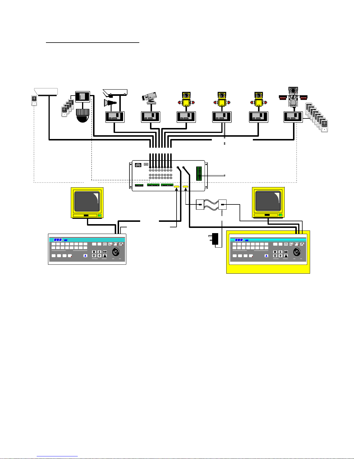
ILLUSTRATION OF Tx1000 SYSTEM
Twisted Pair Telemetry.
Closed loop resistance < 300R
KEYBOARD 1
up the coax telemetry control up to 1Km CT125
Optional Alarm Package
Rx100
domecamera
4localalarms
STATIC
staticcamera
Rx200
staticcamerawithlights/
wash/wipe
Rx200
simpleACpanner
Rx300
ACP/TZoom/Focus
1Aux.
Rx400P
ACP/TZoom/Focus
16Presetswith4Aux.
Rx300M
ACP/TMitsubishi
CCD400control
2Aux.
Rx400DC
High&Variablespeed
P/TZoom/Focus
16Presetwith3Aux.
8Localalarms
alarmcable
Optional
Twisted Pair
OPTIONAL 2ND KEYBOARD
RS232 control Max distance - 50M
Optional
TxLD
available for extended distances.
BBV
300
LENS
LENS
IRIS FOCUS ZOO
M
PROGRAM
#
AUTOPAN
9 10 11 12 13 14 15 16
875 6431 2
CAMERA SELECT
MONITOR
PAN + TILT
PRESETPATROLSEQ
BBV
1000
B B V
300
LENS
LENS
IRIS FOCUS ZOO
M
PROGRAM
#
AUTOPAN
9 10 11 12 13 14 15 16
875 6431 2
CAMERA SELECT
MONITOR
PAN + TILT
PRESETPATROLSEQ
B B V
1000
video in - coax
Tx1000/8 or 16 Base Unit
videoout-coax
TxLD TxLD
Twin Twisted Pair
9V plug PSU
OptionalTxLDlink. Distance>50M.

Tx1000 SeriesTelemetry Transmitter Installation Handbook Rev-01 Page 4of 141
LAYOUT OF THE BBV Tx1000 KEYPAD
Connections
Having mounted the base unit on the wall or in a rack, continue as follows:
1. Connect the keypad to 9-pin d socket marked "Keypad 1".
2. Connect a BNC cable from output M1 to the keypad, and connect the other keypad connection to Monitor 1.
Terminate the cable at the monitor.
3. If the keypad is remotely sited from the base unit, connect the plug-mounted power supply to the keypad via the
2.1mm power connector.
4. Connect either a second spot monitor (no keypad and no text), or the second keypad to Output 2. Note that even if
both keypads are local to the main unit, the second keypad must be powered from the plug-mounted transformer.
5. Connect the BNC cables from the cameras/receivers to the upper BNC sockets in each row, marked "Camera
Inputs".
6. Connect any other equipment requiring the camera video signals to the lower BNC sockets marked "Video Out".
Note that the action of connecting to the video-out socket removes the 75Ωtermination.
7. If the user relay terminals are being used, connect these to the LOW VOLTAGE equipment of your choice.
PIN 6
PIN 7
PIN 8
normally closed
common
normally open
8. Apply power via the IEC connector and switch on. The power LED should flash and the monitors should show
Camera 1 inputs

Tx1000 SeriesTelemetry Transmitter Installation Handbook Rev-01 Page 5of 141
Camera Selection
A camera may be selected onto the controlled monitor by pressing the relevant numbered key.
Monitor Selection
The monitor key has a red LED which is lit when the keypad is controlling the second monitor output. Pressing the
monitor key toggles between the main monitor and the second monitor.
Sequence Activation
Pressing the sequence key will start the sequence on the MAIN monitor. The on-screen display changes from CAM
XX to SEQ XX to indicate that the sequence is running. To stop the sequence, select a camera on the main monitor.
Programming the Sequence Order
Holding down the sequence key causes the sequence to run through the list of inputs at the rate of one per second,
allowing the operator to quickly determine which inputs are/are not in the sequence list. While the sequence key is
held down, any camera key pressed will toggle the inclusion or exclusion of the relevant input. When delivered, all
camera inputs are inluded in the sequence.
Altering the Sequence Delay
This is achieved by pressing the Program key, to gain access to the menu. Sequence delay time may be altered using
Option 9. The on-screen prompt "Seq Delay" appears, inviting the operator to enter a number from 1 to 16 for the
following values:
1
2
3
4
5
6
7
8
9
10
11
12
13
14
15
16
5 seconds
10 seconds
15 seconds
20 seconds
25 seconds
30 seconds
35 seconds
40 seconds
45 seconds
50 seconds
55 seconds
60 seconds
65 seconds
70 seconds
75 seconds
80 seconds
After entering the delay value, the screen clears.
The Triangular-Marked Key
This key activates a relay in the base unit. Pressing the key causes changover contacts to close; releasing the key
opens one set and closes the other. This key may be used by the installer to activate a panic record facility on a VCR,
or to activate a video printer, etc. These contacts are low-voltage, low-current only.
IMPORTANT: DO NOT CONNECT THESE CONTACTS TO MAINS POTENTIALS

Tx1000 SeriesTelemetry Transmitter Installation Handbook Rev-01 Page 6of 141
KEYPAD FUNCTIONS
Pan and Tilt Action:
Press the relevant direction arrow(s)
Lens Action
There are six lens-function switches on the BBV Tx400
keypad. These are Iris Open, Iris Close, Focus Near, Focus
Far, Zoom In and Zoom Out. Press and hold the relevant
key until the desired picture is obtained. Note: If the key is
pressed and held for longer than one second, High Speed
Lens Action is activated. Inching is achieved by repeated
quick presses of the key.
Auxiliary Function Switches
There are four auxiliary function switches on the BBV Tx1000 keypad. These are Wash, Wipe, Autopan and Lights.
Their functions are as follows:
Wash - Press and hold for washer motor to run
Wipe - Latching output, press on/press off
Auto - Press, LED lights up and autopan motor starts. Pressing Left or Right stops Auto
Lights - Latching output, press on/press off

Tx1000 SeriesTelemetry Transmitter Installation Handbook Rev-01 Page 7of 141
SELF TEST
To activate the self test feature for any particular camera reciever, first select that receiver, then press the Program
button and select Menu Option 2. The screen text will clear and Self Test will be activated . See the Rx Series
Telemetry Receiver Installation Handbook for more details.
------------
IRIS LEVEL PROGRAM
To preset the aperture of the iris, press Iris Open or Iris Close until the desired level is reached, then press Program
and Option 3. Note: There is a 15-second time-out, after reaching the correct aperture setting, in which to program
the iris setting. When this time period expires, the iris reverts to its default setting.

Tx1000 SeriesTelemetry Transmitter Installation Handbook Rev-01 Page 8of 141
The remainder of this manual refers to features found only on the Rx400P receiver.
PRESETS
To select a pre-programmed preset, press the Preset key. On the screen, "Preset" will appear. While holding down the
Preset key, select the desired preset number.
------------
To programme a preset, first position the camera using the Up/Down and Left/Right arrows. Then set Zoom and
Focus. When satisfied with the position and the quality of the picture, press Program and select Option 1. When the
on-screen display changes to "Program Preset", enter the number of the preset you wish to program.
To erase a preset, press the Program key to gain access to the menu. Select Option 4 and when the display changes to
"Erase Preset", select the number of the preset to be erased.

Tx1000 SeriesTelemetry Transmitter Installation Handbook Rev-01 Page 9of 141
PATROL SETTINGS
There are two patrol commands that can be started by the BBV Tx1000. They are activated by pressing the Patrol key
and either Key 1 or Key 2. All other keys are ignored. Their function is to enable a string of presets to be selected in
turn, switching between presets after a fixed period of time (nominally 30 seconds).
Note: Once the nominal time period of 30 seconds has been altered, it cannot revert back.
These patrols can be stopped at any time by pressing any of the four arrows on the Pan and Tilt control, when the
reciever on which patrol is running is selected.
To Programme a Patrol
There is no separate patrol-programming function with the BBV Tx1000 keypad. Once a preset has been
programmed, it is automatically included in Patrols 1 and 2.
To Remove a Preset from a Patrol
1. Select the reciever on which the patrol is to run.
2. Press Program to gain access to the menu, then press 5 to remove a preset from Patrol 1 or 6 to remove from
Patrol 2, followed by the preset number to be removed.
This key sequence is illustrated below.

Tx1000 SeriesTelemetry Transmitter Installation Handbook Rev-01 Page 10 of 141
To Programme a Time Period for a Patrol
First, determine the time delay required from the table below:
key 1
key 2
key 3
key 4
key 5
key 6
key 7
key 8
random, 0 to 100 seconds
12 seconds
24 seconds
36 seconds
48 seconds
60 seconds
72 seconds
84 seconds
key 9
key 10
key 11
key 12
key 13
key 14
key 15
key 16
96 seconds
108 seconds
120 seconds
132 seconds
144 seconds
156 seconds
168 seconds
180 seconds
SPARE OUTPUTS
There are four spare outputs, which are momentary-action, for use as relay drivers. They are activated by pressing
simultaneously the # key and one of the auxiliary keys. An on-screen display confirms which output has been
activated.
Andere Handbücher für Tx1000
2
Inhaltsverzeichnis
Andere BBV Sender Handbücher


Beliebte Sender Handbücher anderer Marken


Dejero
Dejero EnGo 3x Bedienungsanleitung

Rosemount
Rosemount 4600 Bedienungsanleitung

Speaka Professional
Speaka Professional 2342740 Bedienungsanleitung

trubomat
trubomat GAB 1000 Bedienungsanleitung

Teledyne Analytical Instruments
Teledyne Analytical Instruments LXT-380 Bedienungsanleitung

Rondish
Rondish UT-11 Bedienungsanleitung


