Blancett B2800 Standard Bedienungsanleitung

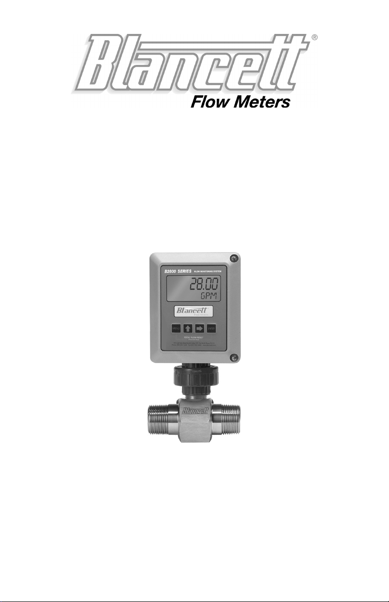
B2800 FLOW MONITOR
- For Liquid Meters -
PROGRAMMING & INSTALLATION
MANUAL
Simplified Version
8635 Washington Ave.
Racine, Wisconsin 53406
Technical Toll-Free: 877.722.4631
Sales Toll-Free: 800.235.1638
Phone: 817.426.2888 Fax: 817.426.5303
www.blancett.com

2
TABLE OF CONTENTS
Introduction……………………..…………………..3
Specifications………………………..…………….....4
Operating the Monitor……………..…………….....5
Programming Mode……………………..…………..6
Programming……..………………….….…...6
K-factor…………….……….…..….………..7
Password………………....……………..…….8
Totalizer………………………………………9
Battery Replacement………………………...9
Additional Input Options……………………………9
Wiring Diagram………….………………………….10
Troubleshooting……………………………………...11
Installation Drawing…………………………………13
Part Numbering Information……………………….14
Statement of Warranty……………………………...15
Notice: Blancett reserves the right to make any changes or
improvements to the product described in this manual at any
time without notice.

3
INTRODUCTION
The B2800 Flow Monitor is a state-of-the-art, microprocessor
based flow monitor, designed to provide the user with exceptional
flexibility at a very affordable price. Though designed for use
with Blancett Flow Meters, this display can be used with almost
any flow meter producing a low amplitude AC output or contact
closure signal(s).
This flow monitor is capable of accepting a low-level frequency
input for calculating flow rate and total. These calculations can
then be displayed in the desired units of measurement. All B2800
flow monitors come pre-calibrated, from the factory, if ordered
with a Blancett Flow Meter. If required, however, it can easily be
re-configured in the field. The monitor’s large 8 digit by .75” nu-
meric liquid crystal display makes extended range viewing practi-
cal. The second 8 digit by .38” alphanumeric display provides for
selectable units viewing in run mode and prompts for variables in
programming mode. Finally, the user can choose between dis-
playing rate, total, or alternating between both rate and total.

4
SPECIFICATIONS
Power Supply Options:
Battery Powered: 1 “D” size 1.5 Volt alkaline battery
Loop Powered: Optional 4-20 mA loop power
Alphanumeric Rate and Total Display:
8 digit, .75” high numeric display
8 character, .38” high alphanumeric display
Fixed or toggle modes of operation for flow rate and totalizer display
Accuracy:
±0.1%
Temperature Drift = 50ppm/°C (Max)
Mounting Classification:
Meter Mount: NEMA 4X Enclosure
Remote Mount: NEMA 4X Enclosure
Swivel Mount: NEMA 4X Enclosure
Environmental:
Operating Temperature: -22 ºF to 158 ºF (-30 ºC to 70 ºC)
Humidity: 0-90% Non-condensing
Inputs:
Magnetic Pick-up input:
Frequency range = 0 to 3500 Hz
Trigger sensitivity = 30 mV p-p
Over voltage protected = ±30 VDC
Outputs:
Opto-isolated open collector transistor
Max. Voltage: 30 VDC
Pulse width: 20mS/Max rate 20Hz
Current (ON state): 0.9V drop @ 5.0 mA or 0.7V drop @ 0.1 mA
Optional 4-20 mA output
Certifications:
CSA: Class I, Div 1 Groups C, D; Class II, Div 1 Groups E, F, G
UL: Class I, II, III Div 1 Groups C, D
CE: IEC 61326-1

5
OPERATING THE MONITOR
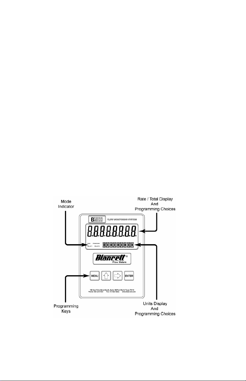
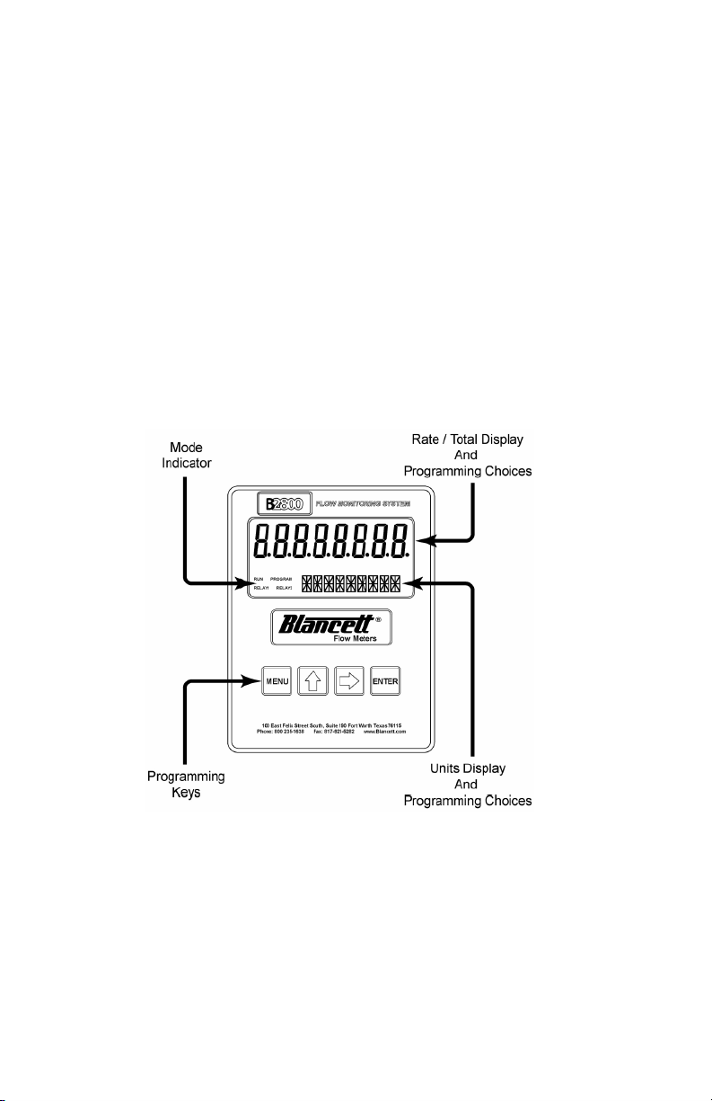
The monitor has two modes of operation referred to as the RUN
mode and the PROGRAM mode. Both the run mode and the pro-
gram mode display screen enunciators confirming the state of the
monitor. A quick glance at the lower left hand corner of the LCD
screen will confirm operating status. Normal operation will be in
the RUN mode. To access the programming mode, press the
MENU button until the first programming screen is displayed.
After programming the display with the necessary information, a
lock out feature can be turned on to prevent unauthorized access
or changing the meter’s setup parameters.
BASIC PROGRAMMING MODE
Keys:
MENU – Switches to Programming mode
UP Arrow – Scrolls forward through the parameter choices
and increments numeric variables
RIGHT Arrow – Scrolls backward through the parameter
choices and moves the active digit to the right
ENTER – Used to save programming information, advance
to the next programming parameter, and in the reset process
Modes:
RUN – Normal operating mode
PROGRAM – Used to program variables into the display
If your monitor was ordered with a Blancett flow meter, the two
components ship from the factory, calibrated as a set. If the moni-
tor is a replacement, the turbine’s K-factor has changed, or the
monitor is being used with some other pulse generating device,
programming will be necessary.

6
Programming Using Pulse Output Turbine
Flow Meters
Each turbine flow meter is shipped with either a K-factor value or
frequency data. If frequency data is provided, the data must be
converted to a K-factor before programming the monitor. K-
factor information, when supplied, can usually be found on the
neck of the flow meter or stamped on the body. The K-factor
represents the number of pulses per unit of volume. The K-factor
will be needed to program the monitor readout.
ENTER PROGRAMMING MODE – Change to program-
ming mode by pressing the MENU button once. The mode
indicator will change from RUN to PROGRAM.
SELECT THE METER SIZE – At the METER prompt,
press the UP or RIGHT arrow keys to select the bore size of
your meter. Press ENTER button once to save meter size
choices and advance to the K-factor units selection.

7
ENTER THE METER’S K-FACTOR UNIT – Directly af-
ter the METER size is selected, the display’s K-factor unit
must be chosen. Use the UP arrow key to select your K-factor
unit. For meters calibrated in gallons, use PUL/GAL (pulses
per gallon), for meters calibrated in cubic meters, use PUL/
M3 (pulses per cubic meter), etc. Press ENTER to save the K-
factor unit and advance to the next parameter.
ENTER THE METER’S K-FACTOR – To change the K-
FACTOR value, use the RIGHT arrow key and select the po-
sition of the number that you wish to change. Using the UP
arrow key, increment the display digit until it matches the me-
ter’s K-factor digit. Repeat this process until all K-factor dig-
its have been entered. Press ENTER once to save the K-factor
and advance to the RATE/TOTAL Units selection.
SELECT THE RATE/TOTAL UNITS OF MEASURE –
The monitor allows the choice of five common rate/total
units. The monitor shows the rate/total unit that the display is
currently set for. If the current selection is current, press the
ENTER key once to advance to the next parameter. To change
to an alternate unit, use the arrow keys to scroll to the desired
rate unit and press ENTER to save the choice.
Note: The meter connection size and the bore size are dif-
ferent. For example, many of the 1” NPT turbines have
bore sizes that range from 3/8” up to 1”. Be sure to use
the correct bore size or the meter will report incorrect
flows and totals.
Note: Unless otherwise specified, Blancett turbine flow
meters are supplied with K-factors measured in pulses per
gallon (PUL/GAL) which will automatically convert to
your desired units of measure.
Note: The K-factor supplied with the meter or calculated
from calibration data will be needed to complete next step.

8
SELECT THE DISPLAY FUNCTION – The monitor can
display RATE or TOTAL or alternate between BOTH rate
and total. If the current selection is correct, press the ENTER

key to advance to the next parameter. To change to an alter-
nate display mode, use the arrow keys to scroll to the desired
display mode and press ENTER to save the choice.
A TEST function is also available in the Display Function
sub-menu. With the test function selected the display acts like
a frequency counter and displays the raw input frequency be-
ing supplied to the frequency input terminals. This is very
useful when troubleshooting flow problems.
TOTALIZER PULSE OUTPUT – The pulse output pa-
rameter can be either enabled or disabled. When enabled this
output generates 20mS duration pulse for every time the least
significant digit of the totalizer increments. The amplitude of
the pulse is dependent on the voltage level of the supply con-
nected to the pulse output and is limited to a max. 30 VDC.
PASSWORD – Password protection prevents unauthorized
users from changing programming information. Initially, the
password is set to all zeros. To change the password, simply
enter any 4 digit code using the arrow keys as previously de-
scribed, enter the password value. Pressing ENTER once will
Note: The total unit’s output multiplier cannot be modi-
fied in the Simplified program level. This option is re-
served in the Advanced program level.
SELECTION RATE TOTAL
GPM/GAL Gallons per Minute Gallons
LPM/LIT Liters per Minute Liters
M3PH/M3 Cubic Meters per Hour Cubic Meters
M3PD/M3 Cubic Meters per Day Cubic Meters
BPD/BBL Oil Barrels per Day Oil Barrels

9
store the password and take you back to the RST PSWD
screen.
RST PSWD – The reset password screen allows the operator
to enter any 4 digit code for the manual reset totals function.
RESET TOTAL – To reset the monitor total display, in run
mode press the MENU and ENTER simultaneously until TO-
TAL RST starts to flash. The TOTAL RST will stop flashing
and the display will return to the run mode at the conclusion
of the reset procedure.
STORE TOTAL – The current total can be manually stored
in the monitor’s flash memory. This procedure may be desir-
able prior to replacing the battery. Press and hold the ENTER
key for 2 seconds. The display will respond with a flashing
TOTALSVD and then return to the run mode.
AUTOMATIC STORE TOTAL – The monitor is equipped
with a store total feature that works automatically, saving the
current total to flash memory. The frequency of saves depends
on the power supply option chosen
Battery Powered: Once per hour and just before a low
battery condition turns the unit off.
Loop Powered: Once every ten minutes.
BATTERY REPLACEMENT – Battery powered monitors
use a single 1.5V, “D” size, alkaline battery. When replace-
ment is necessary, use a clean fresh battery to insure contin-
ued trouble free operation. It is recommended that the total be
saved to memory before the battery is removed. (See STORE
Note: This password will allow the operator to manually
reset totals.
Note: This reset password code will not allow the opera-
tor to enter the programming mode.

10
TOTAL in the programming section of this manual).
Unscrew the two captive screws on the front panel to gain ac-
cess to the battery. Replace the battery being sure to observe
the proper polarity, and then re-fasten the front panel.
ADDITIONAL INPUT OPTIONS
The B2800 Flow Monitor is capable of receiving Magnetic Pick-
up input (small signal sine wave) or a Contact Closure input
(pulse). Since most Blancett Turbine Flow Meters utilize a mag-
netic pick-up, the B2800 flow monitor is shipped configured for
magnetic pick-up input. To change to a contact closure input, re-
move JP2 from the top two pins and jumper them to the bottom
two pins. See Figure 2.
Andere Handbücher für B2800 Standard
5
Inhaltsverzeichnis
Andere Blancett Messgerät Handbücher

Blancett
Blancett B1750 Bedienungsanleitung

Blancett
Blancett B1750 Service-Handbuch

Blancett
Blancett B2800 Standard Bedienungsanleitung

Blancett
Blancett QUIKSERT Bedienungsanleitung

Blancett
Blancett FloClean Service-Handbuch

Blancett
Blancett 1100 Series Bedienungsanleitung

Blancett
Blancett 1200 Service-Handbuch

Blancett
Blancett 1100 Series Service-Handbuch

Blancett
Blancett 900 Series Bedienungsanleitung

Blancett
Blancett B253-102 Bedienungsanleitung