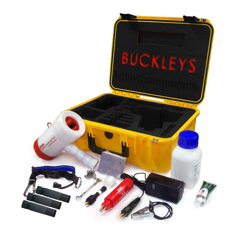
Buckleys BathyCorrometer Pro' Bedienungsanleitung

BathyCorrometer® Pro’
Operating Instructions
English Version
Please read carefully before use

Instruction Manual
2
Contents
Description .........................................................................................................................3
Probe Tips........................................................................................................................3
Shorting Plug...................................................................................................................3
Battery .............................................................................................................................3
Technical data ..................................................................................................................4
Unpacking..........................................................................................................................5
Operation...........................................................................................................................5
BathyCorrometer® Pro’ unit .........................................................................................5
BathyCorrometer® Pro’ Charger.................................................................................6
Calibration.......................................................................................................................... 7
Electronics Calibration Check .....................................................................................7
Test procedure using screw-on K-SAT Reference Electrode.....................................7
Using Zinc & Magnesium test blocks ............................................................................. 10
Replacement of the Screw-In Reference Electrode .................................................. 10
Maintenance ...................................................................................................................11
Safety ................................................................................................................................11
Electromagnetic compatibility ...................................................................................... 12
European Union Directive........................................................................................... 12
Long-term storage ........................................................................................................... 12
Laying-up ...................................................................................................................... 12
Re-Commissioning ....................................................................................................... 12
Disposal information........................................................................................................ 13
EC Declaration of Conformity .......................................................................................14
UKCA Declaration of Conformity .................................................................................. 14
Contact details ................................................................................................................15
Distributor details.............................................................................................................. 15
Product registration.........................................................................................................16

BathyCorrometer
®
3
Description
The BathyCorrometer® Pro’ (BCM) is an underwater corrosion voltmeter powered by
an integral, rechargeable battery pack. The unit is fitted with a 3½ digit, high
impedance (1MΩ) liquid crystal display (LCD) voltmeter.
The unit can read voltages from 0.000V to -1.999V DC. The structure to water
potential is detected by an internal Ag/AgCl/seawater half-cell electrode of robust
and proven construction. The reference electrode is mounted behind the red
protective nose cone and sited 5cm from the probe tip.
Probe Tips
Six stainless steel probe tips are supplied with the instrument. They are provided with
a standard point suitable for use on steel work with coatings of either paint or tape
as used on piles, under sea pipelines and through thicker coatings, marine growth
and similar.
The probe tip is fitted to the front of the instrument by screwing it onto the stainless-
steel stud and tightened with the spanner provided. A definite ‘bottoming’ should
be felt as the probe is screwed fully home. Silicone grease smeared on the outside
of the probe will assist fitting.
Shorting Plug
The unit is activated by use of the shorting plug provided. This should be removed
when the instrument is not in use to conserve battery power. Silicone grease
smeared on the moulded pins of the plug will greatly ease its insertion. The plug
MUST be inserted into the handle socket before the instrument is immersed in water,
otherwise spurious readings and damage to the socket will occur.
Battery
Under normal usage a fully charged battery will provide in excess of 100 hours’
operation. Low battery level is indicated by a battery symbol appearing in the top
left of the LCD display. As the battery is nickel-metal hydride it has the advantage of
no memory effect (unlike nickel-cadmium) and can be charged at any time.
The BCM should only be charged using the charger supplied. Use of an incorrect
charger may damage the electronics and would not be covered by warranty.

Instruction Manual
4
Technical data
BCM unit operating depth: Up to 300m
(pressure tested to 600psi/42bar)
Display: 3½ digit LCD, 12.7mm digit height
Range: 0.00 to -1.999V
DC accuracy: 0.05% typical (±1 count)
Input impedance: >1MΩ
Operating temperature range: 0 to 30°C
Temperature stability: ±100 ppm/°C
Storage temperature range: 0 to 50°C
Operating time (fully charged): 100hr +
Reference electrode: Silver/Silver Chloride Seawater
Accuracy Ag/AgCl: 250mV ±10mV vs SHE at 25°C
Temperature coefficient: -0.6mV °C
Half-cell effective life: 1-2 years
Contact with structure: A4/316 stainless steel probe
Handle bulkhead socket for: On/Off, charging, reference test,
remote readout
Weight in air: 2.5Kg
Weight in water: 0.85Kg negative buoyancy
Instrument size: 100mm diameter x 275mm long
Carrying case size: 505mm x 380mm x 200mm
Charger input voltage: 100V-240V AC 50-60Hz
Charger input current: 100mA
Maximum charger output voltage: 4.8V DC @ 350mA
9.6V DC @ 150mA
Charge indicator: Multi-function red/green LED

BathyCorrometer
®
5
Unpacking
Please check that all items are present in the kit by referring to the relevant
datasheet for your kit (Basic, Standard or Complete).
If any items are missing contact your supplier immediately.
The packaging should be kept for future use should the unit need to be returned for
repair or put into storage.
Operation
BathyCorrometer® Pro’ unit
Fit a stainless steel pointed probe tip to the end of the instrument using a smear of
silicone grease to prevent damage of the O-ring seal. Use the spanner provided to
ensure the probe tip is tightened fully.
Smear the shorting plug pins with silicone grease and insert the plug into the
bulkhead socket in the handle of the BathyCorrometer® Pro’; this switches the
BathyCorrometer® Pro’ on. Screw the shorting plug retaining ring into the handle to
prevent the shorting plug from being accidentally removed.
The BathyCorrometer® Pro’ has been fully tested and calibrated during
manufacture. However, some drying out of the Ag/AgCI/seawater half-cell
electrode may occur, therefore, it is recommended that prior to initial use the unit is
soaked in seawater for a minimum of 30 minutes.
The BathyCorrometer® Pro’ is now ready for use. If required, the calibration can be
checked prior to use, see section entitled ‘Calibration’.
To take a reading under water, push the pointed probe onto the structure ensuring
that a good electrical contact is made to the steel structure.
The structure to seawater potential at that point can now be seen on the display.
After use, wash the BathyCorrometer® Pro’ in clean seawater to remove any debris
from inside the red nose cone then recharge the unit using the battery charger
supplied.
Note: The shorting plug must NOT be removed from the BCM while immersed.
Note: DO NOT immerse the unit in fresh/tap water.

Instruction Manual
6
BathyCorrometer
®
Pro’ Charger
The BathyCorrometer
®
Pro’ battery charger
is supplied with several mains plug options
(European, UK, USA, Australia, Asia), select
the correct configuration for your mains
supply, clicking it into position on the
charger input.
It is recommended that the
BathyCorrometer
®
Pro’ is charged for 8 hours
before initial use. Connect the charger to the BathyCorrometer
®
Pro’. Connect the
charger to the mains supply, the small indicator light on the charger should
illuminate. If the indicator does not illuminate check the connection to the
BathyCorrometer
®
Pro’ and that the mains power is on.
The normal time to recharge the battery from fully discharged is 14 hours, but it can
be left on charge for up to 48 hours without damage to the battery. The battery
may be recharged after use. Allow a charge time of 12 minutes for each hour’s use.
There is no indication on the charger or the BathyCorrometer
®
Pro’ that the battery is
charged. If the charger is turned off it will not discharge the BCM. When charging is
complete, disconnect the charger from the mains supply and then from the
BathyCorrometer
®
Pro’.
Note: The BathyCorrometer® Pro’ is NOT compatible with
older BathyCorrometer chargers and MUST only be charged
with a BathyCorrometer® Pro’ Charger.
Similarly, the charger provided with this unit is NOT
compatible with earlier models, and should not be used to
charge them.

BathyCorrometer
®
7
Calibration
Electronics Calibration Check
1. The electronics in the BCM/BCM Pro’ can be checked with the aid of the
CalChecker Pro’. When connected to the BCM/BCM Pro’, this produces a
precision voltage of -1.900V DC which can be compared with the reading on
the BCM/BCM Pro’. This is just a check as the electronics are contained inside
the pressure housing and cannot be adjusted without breaking the seal.
2. If the BCM/BCM Pro’ is more than ± 2mV out from the -1.900V test voltage,
firstly check the battery in the CalChecker Pro’. If necessary, replace with a
CR1632 standard lithium primary button cell (1002-0026). Then ensure the
CalChecker Pro’ is not at fault. This can be carried out using a calibrated
precision multimeter. If the CalChecker Pro’ is within specification, it is
advised that the BCM/BCM Pro’ should be returned to the manufacturer or
certified test house for repair.
3. The warranty will be void if repairs are undertaken by anyone other than the
manufacturer or a certified test house.
Test procedure using screw-on K-SAT Reference Electrode
The BathyCorrometer
®
may be checked with the aid of verification tools either
purchased with this kit or available separately.
The K-SAT electrode provides a stable, known voltage to calibrate the
BathyCorrometer
®
. The reference electrodes are accurate external reference
electrodes with an Ag/AgCl element contained in a potassium chloride solution of
known chloride content. The reference voltage produced by the K-SAT cell is 196mV with
respect to a Standard Hydrogen Electrode.
IMPORTANT
BathyCorrometer® recalibration should only be undertaken by Buckleys trained
and approved technicians with access to the appropriate electrical and pressure
testing equipment.
Recalibration by unqualified technicians will invalidate the BathyCorrometer’s
warranty.
Note: If checking the calibration of an older BCM, connect the short lead
between the CalChecker Pro’ and the BCM’s stainless steel probe tip.

Instruction Manual
8
The effect of this is that the voltage reading obtained by a correctly-functioning
silver-silver chloride (Ag-AgCl) half-cell in 3% sea water at 25C will be approximately
-54mV for the K-SAT cell.
As with all Silver-Silver Chloride chemistry, the exact voltage obtained will depend
on the conditions, particularly water temperature and salinity. A tolerance of +/-
10mV for the K-SAT cell indicates acceptable performance.
The following instructions should be used to check the calibration of the
BathyCorrometer
®
Pro’.
1. Unscrew the white Delrin probe cone.
2. Smear the O-ring on the K-SAT reference electrode with a
little silicone grease.
3. Screw the K-SAT reference electrode onto the threaded tie Rod,
ensuring a tight connection and correct seating of the O-ring.
Unscrew the K-SAT end cap to remove it.
4. Fit the shorting plug (6004-0019) and immerse the BCM/BCM Pro’ in seawater
test solution (3% salinity), ensuring that the level covers the red nose cone. The
ideal temperature for the water is 20-25°C. Note for mixture 300 grams to 10
litres of de-ionised water.
5. Allow the electrode to reach a stable potential (10 to 15 minutes). The
voltage difference between the K-SAT electrode and the internal silver/silver
chloride electrode can be read directly off the digital display on the
BCM/BCM Pro’.
Screw cap Threaded tie rod
BathyCorrometer® Pro’ Body

BathyCorrometer
®
9
6. The voltage difference between the K-SAT electrode and the internal
silver/silver chloride electrode can be read directly off the digital display on
the BCM/BCM Pro’.
The test should be repeated with another K-SAT to confirm the accuracy of the
internal Ag/AgCl/seawater half-cell electrode.
Remove the K-SAT cells, refit their protective caps, wipe down and store in a cool
dark place.
Plastic container
Seawater test
solution 3% salinity
Voltage difference between K-
SAT reference electrode and
Ag/AgCI electrode
-54mV ± 10mV
Note: The protective caps should ALWAYS be fitted whenever the K-SAT cells
are not in use.
Note: The values recorded for the silver/silver chloride electrode are
dependent upon the salinity and temperature of the seawater at the time of
measurement.
Note: Mixture 300
g
rams to 10 litres of deionised water.
Note: The BCM Pro’ displays results as a negative reading i.e. -54mV ±
10mV (K-Sat cell)
Note: Never allow water to enter the hole at the top of the K-SAT

Instruction Manual
10
Using Zinc & Magnesium test blocks
Verification of the operation of the BCM Pro’ can be carried out using Zinc and/ or
Magnesium test blocks. Potential measurements taken should be noted to check if
any significant variation occurs. Differences in the order of 10mV or so between
readings are quite possible and will mainly be caused by variations in water salinity
at different locations and/or changes in water temperature. As a guide, readings
taken in a 3% salinity solution at ambient temperature of 25°C are as follows:
Zinc (Zn) = -1.00 to -1.08V
Magnesium (Mg) = -1.40 to -1.70V
Tarnished blocks will give a lower reading than clean ones. The test blocks should
not be left in the seawater after use. Only one test block should be used at a time.
Replacement of the Screw-In Reference
Electrode
Remove the stainless steel probe tip - if fitted - using an 8mm spanner.
Using a 19mm spanner, remove the white delrin probe cone.
Remove the stainless steel slotted nut and washer from the tie rod, using the nose
cone peg spanner (6005-0500).
Gently ‘rock’ and remove the red nose cone, which will expose the black plastic
reference electrode.
Carefully unscrew the reference electrode.
Ensure that there are no foreign bodies in or around the seat of the reference
electrode and the O-ring around the tie rod.
Smear the O-ring and the thread on the new reference electrode with silicone
grease (4004-0017).
Screw in the new reference electrode until the O-ring just seats, then tighten half a
turn and no more. Over tightening the reference electrode could damage the
thread.
Replace the red nose cone, ensuring that there is no debris or foreign matter
around its seat, and that the cut out is positioned to accommodate the reference
electrode.
Replace the stainless steel washer and slotted nut and tighten so there is no gap
between the red nose cone and the white body.
Andere Handbücher für BathyCorrometer Pro'
2
Inhaltsverzeichnis
Andere Buckleys Messgerät Handbücher