BYK CAP 1000+ Bedienungsanleitung

Additives & Instruments
A member of
Measure what you see.
CAP 1000+ Viscometer
Manual

CAP 1000+ Viscometer
Manual
BYK-Gardner GmbH
Lausitzer Str. 8
D-82538 Geretsried
Germany
Tel. 0-800-gardner
(0-800-4273637)
+49-8171-3493-0
Fax +49-8171-3493-140
BYK - Gardner USA
9104 Guilford Road
Columbia, MD 21046
USA
Phone 800-343-7721
301-483-6500
Fax 800-394-8215
301-483-6555
www.byk.com/instruments
199 024 584 E 1610

4
Dear customer,
Thank you for purchasing a BYK-Gardner Product, BYK-Gardner is committed
to providing you with quality products and services. We offer complete system
solutions to solve your problems in areas of color, appearance and physical
properties. As the basis of our worldwide business, we strongly believe in total
customer satisfaction. Therefore, in addition to our products, we offer many
VALUE-ADDED services:
- Technical Sales Force
- Technical & Application Support
- Application and Technical Seminars
-Repair&CerticationService
BYK-Gardner is part of the Additives and Instrument Division of ALTANA AG, a
leading supplier of additives for coatings and plastics. Together, we offer complete
anduniquesolutionsforyouourcustomer.Thankyouforyourtrustandcondence.
If there is anything we can do better to serve your needs, do not hesitate to let us
know.
Your BYK-Gardner Team

5
Table of Contents
TABLE OF CONTENTS
I. INTRODUCTION .................................................................................................... 7
I.1 Components........................................................................................................... 8
I.2 Utilities.................................................................................................................... 9
I.3Specications......................................................................................................... 9
I.4 Installation ............................................................................................................ 10
I.5 Safety Symbols and Precautions ......................................................................... 11
I.6 Key Functions....................................................................................................... 12
I.7 Viscosity and Temperature Display ...................................................................... 13
I.8 Cleaning ............................................................................................................... 13
II. GETTING STARTED ............................................................................................. 14
II.1 Power ON ............................................................................................................ 14
II.2 Cone Spindle Selection and Setting.................................................................... 14
II.3 Speed Setting...................................................................................................... 16
II.4 Temperature Control Setting ............................................................................... 16
II.5 Hold Time Settings .............................................................................................. 17
II.6 Run Time ............................................................................................................. 17
II.7 Printing ................................................................................................................ 17
II.8 Run and Stop Keys.............................................................................................. 18
III. OPERATION ........................................................................................................ 19
III.1 Accuracy of Measurement.................................................................................. 19
III.2 Repeatability....................................................................................................... 20
III.3 Making Viscosity Measurements........................................................................ 20
APPENDIX A - Cone Numbers, Sample Sizes, Viscosity Ranges ....................... 23
APPENDIX B - Calibration Procedures.................................................................. 26
APPENDIX C - Variables in Viscosity Measurement ............................................ 29
APPENDIX D - Warranty Repair and Service ........................................................ 31

6
7
Introduction
I. INTRODUCTION
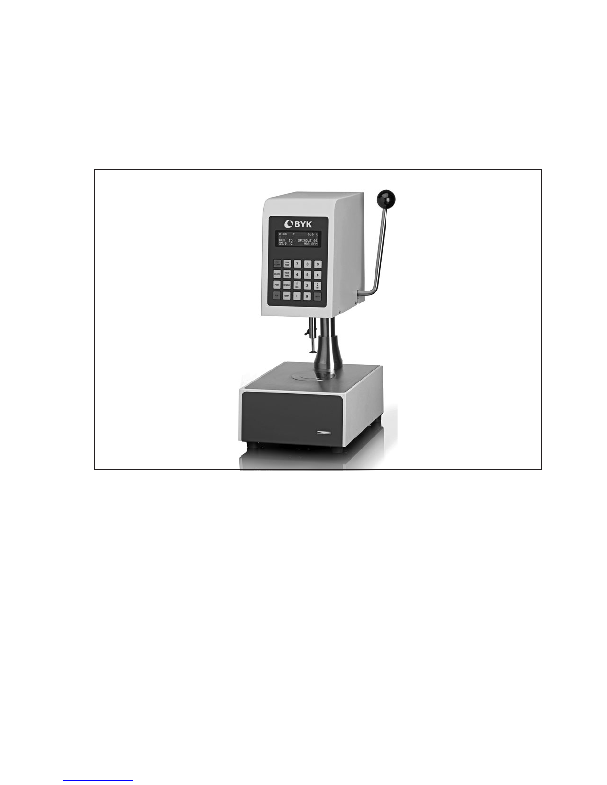
The CAP Series Viscometers are Cone and Plate geometry high shear rate
instruments with integrated temperature control of the test sample material. The
CAP1000+isaxedshearrateviscometerrotatingat750RPMand900RPM.
The instruments operate by digital setting and display; rotational speed can be
automatically timed to stop. High shear rate viscosity measurements are made
over various viscosity ranges depending upon the cone spindle and the rotational
speed (shear rate). Viscosity is selectively displayed in units of centipoise (cP), poise
(P),milliPascalseconds(mPa•s)orPascalseconds(Pa•s).Temperaturecontrolof
sample is possible between either 5°C (or 15°C below ambient, whichever is higher)
and 75°C or 50°C and 235°C depending on viscometer model.
The CAP1000+ can also be ordered with a single, customized speed between 5 and
1000 rpm. In this case, the CAP can offer, when necessary, low shear rate capability.
The CAP 1000+ Viscometer selectable display in either the CGS or SI units
(see page 7):
CGS SI Comment
Viscosity: P or CP Pa•sormPa•s 0.1Pa•s=1P(=100cP)
Shear Rate: SEC-1 SEC-1
Speed: RPM RPM
Temperature: °C °C
The CAP 1000+ Viscometer output data to a parallel printer in the CGS and SI units:
CGS SI Comment
Viscosity: P or cP Pa•sormPa•s 0.1Pa•s=1P(=100cP)
Full Scale Range (F.S.R.): % %
Shear Stress: Dynes/cm2 N/m2 1.0N•m=107dyne•cm
Shear Rate: SEC-1 SEC-1
Speed: RPM RPM
Run Time: Seconds Seconds
Temperature: °C °C
Cone Spindle Number: No. No.

8
Components
I.1 COMPONENTS
The following items are included:
PART NO.
1. CAP 1000+ Viscometer
2. Cone Spindle(s) 7531 through 7536, 7560 through 7563
3. Spindle Case CAP-106Y
4. Solvent Trap CAP-118
5. Power Cord: 115V DVP-65
220V DVP-66
UK DE-8
Germany DE-7
6. Operating Instructions Manual M/02-313
The following optional items may have been included:
7. Viscosity Standard Fluid for calibration See Table A-1 in Appendix A
Please check to be sure that you have received all components, and that there is
no damage. If you are missing any parts, please notify BYK-Gardner or your local
BYK-Gardner representative immediately. Any shipping damage must be reported to
the carrier. Save the packing container, if possible, for future use when returning the
viscometer to BYK-Gardner or an authorized dealer for service.
Head Serial Tag Info
on Back of
Viscometer Head
Handle for Raising
and Lowering
Viscometer Head
Column
Foam Shipping Insert
P/N CAP-122
Base
Console
Cone Spindle
P/N CAP-S-XX
The
Flat
Solvent Trap
P/N C1K-63
Thumb Screw
P/N CAP-85Y
Figure I-1: Components

9
Utilities/Specications
I.2 UTILITIES
Input Voltage: 115 VAC or 230 VAC
Input Frequency: 50/60 Hz
Power Consumption: Less than 345 WATTS
Fuses: (2) 5x20mm, 3A, 250V, Fast Acting for 125VAC
(2) 5x20mm, 1.6A, 250V. Fast Acting for 250VAC
Power Cord Color Code:
United States Outside United States
Hot (live) Black Brown
Neutral White Blue
Ground (earth) Green Green/Yellow
I.3 SPECIFICATIONS
Speeds: 750 RPM and 900 RPM or single speed from 5-900 RPM as
speciedattimeoforder(seeinstrumentserialtag)
Temperatures: CAP 1000+L 5°C (or 15°C below ambient, whichever is higher) to 75°C
CAP 1000+H 50°C to 235°C All models provide 0.1°C increments
Weight: Gross Weight 36 lb 16.3 kg
Net Weight 27 lb 12.3 kg
Carton Volume 4.9 cu ft 0.15 m3
Carton Dimensions 18 in. L x 18 in. W x 26 in. H
48 cm. L x 48 cm. W x 66 cm. H
Materials: CAP cone spindles and temperature plates are made of tungsten carbide.
Operating
Environment: CAP 1000+ Viscometers must be operated within the following
ambient temperatures: +5°C (41°F) to 40°C (149°F)
and humidity: 20% to 80% R.H. (non-condensing atmosphere)
ElectricalCertications/ConformstoCEStandards:
BSEN 61326: Electrical equipment for measurement, control and laboratory use -
EMC requirements.
BSEN 61010-1: Safety requirements for electrical equipment, for measurement,
control and laboratory use.
Airborne Noise Emissions - Levels do not exceed 70 dB(A).
NOTICE TO CUSTOMERS:
This symbol indicates that this product is to be recycled at an appropriate collection center.
Users within the European Union:
Please contact your dealer or the local authorities in charge of waste
management on how to dispose of this product properly. All BYK-
Gardnerofcesandournetworkofrepresentativesanddealerscanbe
found on our website: www.byk.com
Users outside of the European Union:
Please dispose of this product according to your local laws.
10
Installation
I.4 INSTALLATION
NOTE: DO NOT lift the viscometer by the handle or display panel!
LIFT by the base console or column!
1) Set the viscometer on a clean level bench surface.
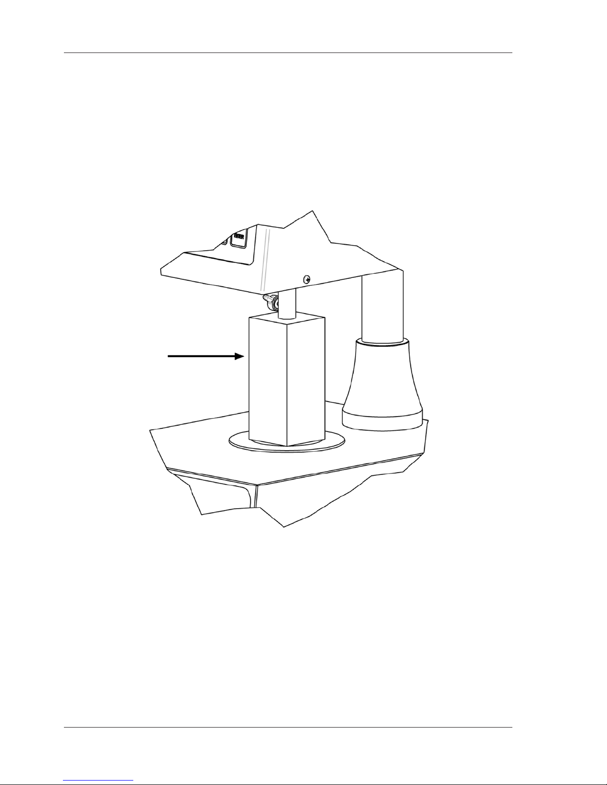
2) Remove shipping spindle blank and foam packing from CAP Viscometer. Store
the spindle blank in the spindle case. Use again only when transporting CAP
Viscometer.
3) Verify that the viscometer’s power requirements match your power source
BEFORE connecting it to power.
The AC input voltage and frequency must be within the appropriate range
as shown on the name plate of the viscometer.
NOTE: The CAP Viscometer must be earth grounded.
Use the three (3) wire power cord! Do not alter!
4) Connect the power cord to the viscometer and to the power supply (source).
5) If using a printer, connect the printer cable to the printer port and printer.
NOTE: Ensure that both the printer and the CAP-1000+ are off when connecting
cables.
Foam Insert Used
When Shipping
CAP Viscometer
Figure I-2: Detail of Foam Insert
Inhaltsverzeichnis
Andere BYK Messgerät Handbücher

BYK
BYK haze-gard plus Bedienungsanleitung

BYK
BYK micro-TRI-color 345 000 015 Series Bedienungsanleitung

BYK
BYK micro-TRI-gloss ? Bedienungsanleitung

BYK
BYK spectro2profiler Handbuch

BYK
BYK spectro2guide Bedienungsanleitung

BYK
BYK LCM III Bedienungsanleitung

BYK
BYK LC 4 Bedienungsanleitung

BYK
BYK haze-gard plus Bedienungsanleitung

BYK
BYK micro-TRI-gloss ? Bedienungsanleitung

BYK
BYK micro-TRI-gloss ? Bedienungsanleitung


