
Cablescan 90 Series Bedienungsanleitung

CABLESCAN
SERIES
90
REFERENCE MANUAL
SECTION 2.0, PART 1
SETUP -S.ERIES 90 AND SERIES 90HV
August 3, 1995
Page
ii
2.0 Setup -Series 90/90HV

2.0 Setup -Serjes 90/90HV Page
iii
• TABLE OF CONTENTS
UNPACKING......................................................................................................................1
POWER CONNECTION.....................................................................................................1
POWER CORDS........................................................................................................1
GROUNDING THE UNIT ........................................................................................2
CHANGING POWER SETTING..............................................................................4
FUSE REPLACEMENT............................................................................................5
SYSTEM SETUP ................................................................................................................7
CONTROLLER .........................................................................................................7
• EXPANSION CABINETS.........................................................................................8
ADDITIONAL EXPANSION CABINETS...............................................................8
COLOR MONITOR...................................................................................................9
KEYBOARD..............................................................................................................9
SCANNER BOARDS ..............................................................................................
10
SCANNER BOARD JUMPERS..............................................................................
11
CONFIGURATION.................................................................................................
12
Discussion.......................................................................................................
12
Configuring 486-Based Systems ....................................................................
13
Configuring 386-Based Systems ....................................................................
16
Configuring 286-Based Systems ....................................................................
19
•

Pageiv
2.0 Setup -Series 90!90HV
TABLE OF CONTENTS -CONTINUED
SOFTWARE
AND
FIRMWARE
......................................................................................
21
SOFTWARE
UPDATES .........................................................................................
21
Description......................................................................................................
21
Software Installation.......................................................................................
23
SERIES 90
FIRMWARE
.........................................................................................
23
Description......................................................................................................23
Firmware Update Procedure ...........................................................................23
HARD
DISK
SETUP...............................................................................................26
Directory Structure .........................................................................................26
AUTOEXEC.BAT
File...................................................................................26
CONFIG.SYS File..........................................................................................26
REMOTE
SIGNALS .........................................................................................................27
DISCUSSION ..........................................................................................................27
VACUUM
FIXTURE
OPERATION
.......................................................................28
OUTPU'[
CONNECTOR
.........................................................................................28
HANDLING
CIRCUIT
BOARDS
.....................................................................................29
SHIPPING
AND
STORAGE ............................................................................................29

2.0 Setup -Series
90/90HV
Page v
LIST OF FIGURES
Figure Description Page
1 Series
90/90HV
Power Connections 3
2 Power Setting Location 4
3 Fuse Locations -Expansion Cabinet 6
4 System Controller Board Locations 7
5 Controller and Expansion Cabinet Hookup 8
6 Color Monitor and Keyboard Hookup 9
7 Scanner Board Locations 10
8 Scanner Board Jumpers.
11

Page vi 2.0 Setup -Series
90/90HV

2.0 Setup -Series 90/90HV
Page
1
UNPACKING
The major components
of
the Series 90/90HV are packaged in foam-packed shipping cartons.
Carefully unpack the components, and set the containers aside for future use. Visually inspect
each component for damage or deficiency. Record any deficiencies and report them
to
Cablescan. In the event the equipment has been damaged as a result
of
shipping, notify the
carrier and Cablescan immediately.
The Series 90/90HV will consist
of
a minimum
of
three containers:
1.
System Controller
2.
Expansion Cabinet
3.
Keyboard, VGA Color Monitor, and Manuals
Depending on the capability ordered, there may
be
other containers for additional expansion
cabinets. The optional printer is also shipped in an individual container.
POWER CONNECTION
Before applying power
to
the Series 90/90HV, make sure that the operating voltage
is
correct and
the unit
is
properly grounded (see GROUNDING THE UNIT, below). For changing voltage
settings see CHANGING POWER SETTING, below.
POWER
CORDS
All power cords are supplied with North American type plugs. The plug ends must be replaced
for countries with another standard. To help make the change easier, the power cord wires are
coded with the International color code standard. A translation table for the North American and
International color code standards
is
provided below.
COLOR
CODE
GROUND
green/yellow green

Page 2 2.0.Setup -Series 90!90HV
CONNECTION PROCEDURE
Arrange the Series 90/90HV with the system controller alongside the expansion cabinet.
Connect the power cords as shown in Figure
1,
and as described below:
1.
Connect a power cord (part number 9200016) from the INPUT power connector
(male) on the rear panel
of
the expansion cabinet to an AC receptacle.
2.
Connect the jumper power cord (part number 9200067) from the female receptacle
on the far left
of
the expansion cabinet to the INPUT power connector (male) on the
system controller. The female receptacle on the expansion cabinet is controlled by
the power switch on the front panel. By connecting the system controller to the
expansion cabinet and leaving the system controller's power switch on, both units
can
be
switched on using the expansion cabinet On/Offswitch.
3.
Connect a second power cord (part number 9200016) from the INPUT power
connector (male) on the color monitor to an
AC
receptacle. (The color monitor may
have an attached cord.)
GROUNDING
THE
UNIT
Each component
of
the Series 90/90HV is shipped with a three-wire grounded cable. When the
cable is connected to a three-wire (grounded) receptacle, it connects the chassis
of
the unit to
ground.
WARNING
Continuity
of
the
grounding circuit
is
vital for the safe operation
of
the
units. Never operate the Series 90/90HV through
an
ungrounded
connector,
or
with the grounding conductors disconnected.

2.0 Setup -Series 90/90HV
Page
3
Expansion
Cabinet (Series 90E9
shown)
AC Source
2.
System
Controller
1.
3.
Monitor
1.
Connect Expansion Unit Power Cord to AC source.
2.
Connect Jumper Power Cord from Expansion Cabinet to Controller,
3.
Connect Monitor Power Cord to AC source.
text
1.
Povv'er
Connections
Page 4 2.0 Setup -Series 90i90HV
CHANGING
POWER
SETTING
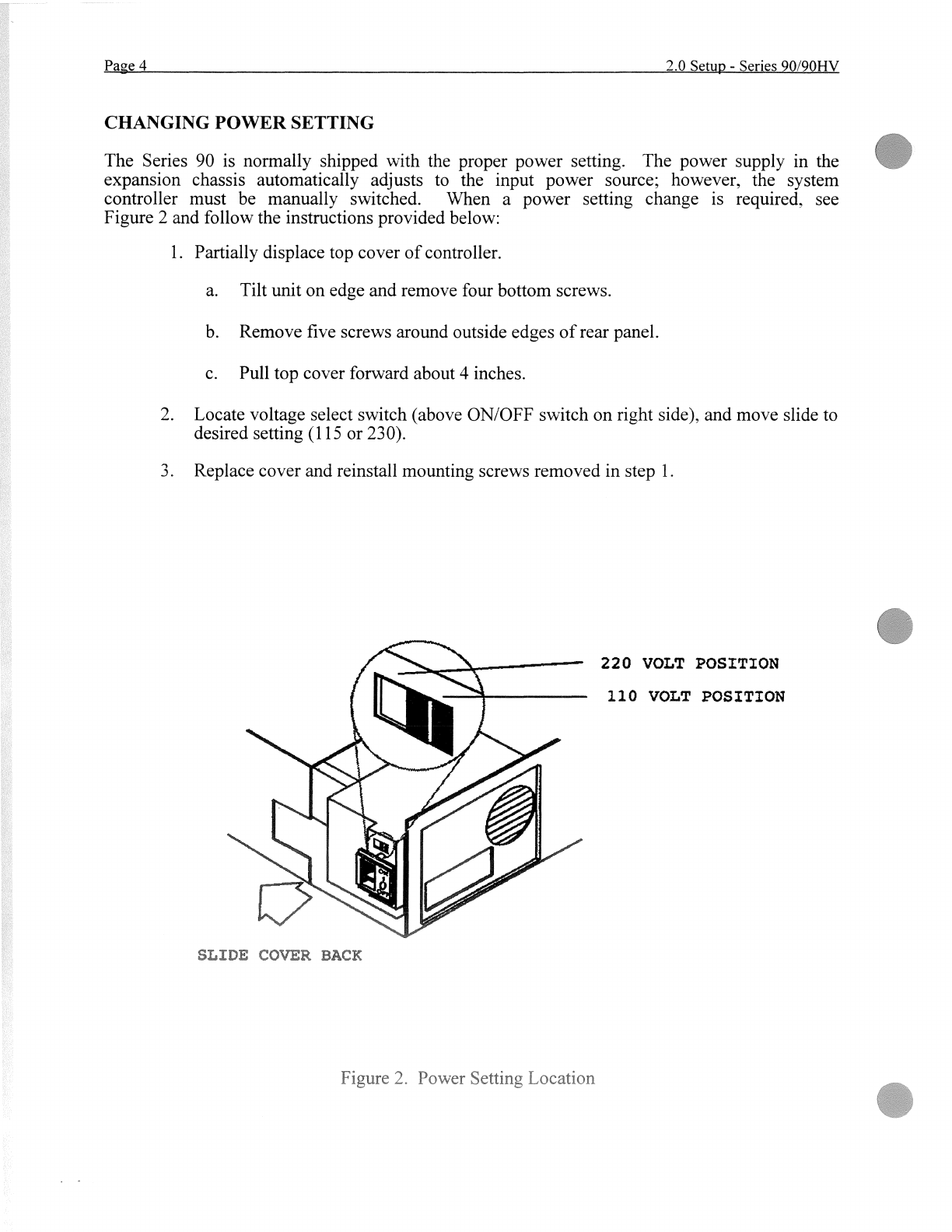
The Series 90 is normally shipped with the proper power setting. The power supply in the
expansion chassis automatically adjusts to the input power source; however, the system
controller must be manually switched. When a power setting change is required, see
Figure 2 and follow the instructions provided below:
1.
Partially displace top cover
of
controller.
a.
Tilt unit on edge and remove four bottom screws.
b.
Remove five screws around outside edges
of
rear panel.
c.
Pull top cover forward about 4 inches.
2.
Locate voltage select switch (above ON/OFF switch on right side), and move slide to
desired setting (115 or 230).
3.
Replace cover and reinstall mounting screws removed in step
1.
L
220
VOLT
POSITION
110
VOLT
POSITION
Andere Handbücher für 90 Series
2
Dieses Handbuch passt für folgende Modelle
3
Inhaltsverzeichnis
Andere Cablescan Messgerät Handbücher


