Dill TPMS 1502 Handbuch

Thank you for purchasing the Dill TPMS Trailer Kit. Properly inflated tires
increase fuel economy, reduce tire wear, and increase handling. A warning
system to notify you of an underinflated tire will help give you time to respond
prior to potentially damaging your tire or trailer.
For more information visit our website at http://www.trailertpms.com
Key Features:
Visual and audible warnings
Set desired PSI levels
Adjustable windshield mount
included
Alerts when tire
pressure is too
low or too high
Alerts when tire
temperature is
too high
Easy Plug-In DC power source
Adjustable Angle Valve Stems fit
a variety of wheels

2
Table of Content Page
1. System Overview: 3
1.1 System Components 3
1.2 How the System Works 3
1.3 Display indicators and Controls 4
1.4 Transmitter Components 4
1.5 Position of Transmitter and ID Module 5
2. Transmitter Installation & Position 6-7
3. Using TPMS Unit: 7
3.1 Getting Started 7-8
3.2 Transmitter Activation 8
3.3 Cold Inflation Pressure Setting 9
3.4 Restore Default Setting 9
3.5 Normal Monitoring 9
3.6 Warnings 9-11
3.7 Antenna Installation & RF Interference 11-12
3.8 Tire Rotation 13
3.9 Replace Transmitter and ID Module 13
4. Specifications: 14
4.1 Transmitter 14
4.2 Display Unit 14
4.3 Component Part Numbers 14
4.4 Available Valve Configurations 15
3.10 Restart System 13

3
1. System Overview
As a vehicle safety device, the TPMS trailer kit monitors tire pressure and
temperature. It will provide warnings about abnormal conditions such as low
pressure, high pressure, and high temperature.
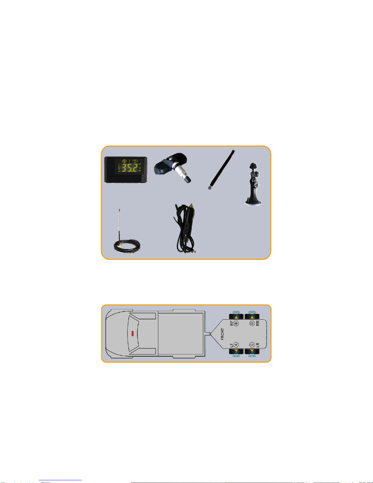
1.1 System Components
1.2 How the System Works
A transmitter is installed in each wheel with an aluminum valve stem and
monitors the pressure and temperature conditions inside each wheel of the
vehicle. This data is wirelessly sent to the receiver that is installed on the
vehicle. The receiver displays the pressure and temperature for each tire
position. When an abnormal condition is detected, the display will alert the
driver.
DISPLAY
DISPLAY
MOUNT
TRANSMITTERS
EXTERNAL
ANTENNA
(IF NEEDED)
DISPLAY
UNIT ANTENNA
12V DC POWER
CORD & HARDWIRE
CONNECTION

4
1.3 Display Indicators and Controls
PRESSURE
UNIT
RIGHT FRONT TIRE
RIGHT REAR TIRE
TEMPERATURE
UNIT
ABNORMAL ICON
CYCLE BUTTON
LEFT REAR TIRE
LEFT FRONT TIRE
CHIP IDENTIFIER
LOCATION FOR
TRANSMITTERS
ANTENNA
SET KEY
RESTORE KEY
1.4 Transmitter Components
NOTE:
Only plastic (non-chrome) caps
and nickel plated valve cores can
be used as replacement.
HEX NUT
RUBBER GROMMET
METAL WASHER
VALVE STEM
VALVE
CAP
ELECTRONIC
TRANSMITTER
SCREW
LOCK
WASHER

5
1.5 Position of Transmitter and ID module
Note the default installation position of the transmitter and ID modules as
illustrated. A letter identifier marked on the transmitter, ID module, and hex nut
is shown on each component.
The letters “LF/RF/LR/RR” on the back of the display unit correspond to the
tires’ respective positions. Each pair of transmitter and ID module need to be
installed in the same position.
To access the ID modules, pull the ID module cover away from the display unit.
For example, if you install transmitter “A” in the left front tire, then you should
plug the ID module “A” in “LF” position on the receiver.
NOTE: When installing the ID chips into the display unit verify the ID letters are facing
towards the back of the display and is in the correct orientation. Small clip must
face the back, regardless if the letter identifier is facing the wrong orientation.
Transmitter I.D.
ID MODULE COVER
I.D. Module
1101143
080908-1101134
Hex Nut I.D.
C
Small clip must
face towards the
back of the display.
Large clip
faces towards
front of display.

6
2.2 Place the valve stem onto the transmitter and use the lock washer & screw
to hold valve stem against the transmitter body.
Note: DO NOT TIGHTEN THE SCREW.
2.3 Insert the valve stem through the rim hole and verify that the rubber
grommet is seated against the rim hole surface.
2.4 Adjust the angle of the transmitter body and verify the transmitter is resting
flat against the wheel rim surface.
2.5 Tighten the screw at 35 inch pounds into valve stem at the same time verify
3 conditions:
2.5.1 At least one of the transmitter’s feet always contacts the rim surface.
2.5.2 The grommet is fully seated against the valve hole.
2.5.3 From the outside of the wheel, the valve stem is perpendicular to the
rim’s valve hole.
2.6 Place the metal washer and hex nut on the valve stem and turn the hex nut
clockwise until the rubber grommet is pressed against the wheel rim
surface.
2.7 Tighten the hex nut 35 to 40 inch pounds of torque to secure the valve stem
to the rim. Verify at least one of the transmitter’s feet has direct contact on
the wheel rim surface. If not, uninstall the transmitter and redo it from 2.5.
2.8 Lock the wheel rim on the tire changer.Apply lubricant on both tire beads
and rim. Mount the lower tire bead on the rim. Ensure that the tire bead
does not touch the electronic module during mounting.
2.9 Mount the upper tire bead the same way and inflate the tire to standard cold
inflation pressure. Avoid damaging the antenna.
Wheel Mount
Head
Transmitter
Transmitter
Wheel Mount
Head
2.0 Transmitter Installation
Before installation into the rim hole, you must assemble the transmitter and
valve stem together.
2.1 Unscrew the hex nut and remove the metal washer from the valve stem.

7
3. Using TPMS Unit
3.1 Getting Started
3.1.1 Install the supplied antenna to your display unit located at the back of the
unit.
3.1.2 Use the display mount to affix the display unit on the windshield or
dashboard. Do not block the driver’s view. Adjust the viewing angle of
the display, if necessary.
2.10 Apply suds on the valve tip, grommet / rim seal. If no leakage is found,
install the valve cap. Otherwise, re-inspect and resolve leak issue.
2.11 Dynamically balance the wheel before it is put back on the vehicle.
2.12 Visually inspect the wheel rim, valve stem, and electronic module to
ensure no damage has occurred. Pressurized the tires to your desired
cold inflation setting.

8
An immediate audible “Beep” sound will indicate the display unit is on. In 2 to 3
minutes, the display unit will show the tire pressures in yellow, along with four
blue tire position lights.
3.2 Transmitter Activation
Note: reference section 2 for transmitter installation.
The transmitters are shipped in “sleep” mode for battery conservation and will
be activated when the transmitter detects pressure in the tires or when the
vehicle speed exceeds 20mph.
The default cold inflation pressure setting of the display unit is 35PSI. The
display unit is programmed to provide a low pressure warning when the
pressure is 20% lower (28PSI) and 30% higher (46PSI).
PSI LEVEL 20% LOWER 30% HIGHER
35 28 46
50 40 52
80 64 104
Cold inflation pressure can be set to your desired pressure and a warning will
alarm at 20% below and 30% above this pressure. For example, the driver will
be alerted at the following low and high pressures base on various set pressure:
3.1.2 Plug the power cord into the display unit and plug the adapter into
auxiliary power supply.

9
3.5 Normal Monitoring
3.5.1 Stationary State:
The transmitter will detect tire pressures and temperatures at 8-
second intervals and transmit the data to the display at 2-minute
intervals as long as they are normal. As the data is received, the
display will refresh.
3.5.2 Moving State:
The inertia switch of transmitter is on when the speed exceeds
16mph.
The transmitter will detect tire pressures and temperatures at
4-second intervals and transmit the data to the display at 30-second
intervals as long as they are normal. As the data is received, the
display will refresh.
3.5.3 Normal Data Display:
The display will automatically circulate among the tire positions in the
following order LF/RF/RR/LR.
Press and release the “Cycle Button” to view the tire temperatures.
3.6 Warnings
3.6.1 Low Pressure Warning
If the current pressure in a tire is 28PSI or lower in default mode or
20% lower than the cold inflation pressure setting, then the following
will occur:
3.3 Cold Inflation Pressure Setting
Cold inflation pressure setting is pre-set at the to 35PSI, when installation and
replacement of each transmitter and ID modules.
To change cold inflation pressure setting, perform the following:
3.3.1 Inflate the tire pressures to the recommended cold inflation pressure.
3.3.2 Press the “SET” key on the back of display and hold for 8 seconds to
enter new cold inflation pressure setting.A‘beep’ will sound and all
indicator lights will turn off and the screen display will show “ddd”.
Allow 3 to 5 minutes for the receiver to accept new cold inflation
pressure setting.
3.3.3 To check a tire’s cold inflation pressure setting, press and release the
“Cycle Button” twice. Repeating this step will cycle through each
tire’s pressure setting.
3.4 Restore Default Setting
To switch to default setting, press and hold the “RESTORE” key for 3 seconds.
The display unit will switch back to default operations within 30 seconds.

10
1. The display will show the pressure of the abnormal tire and the
digits will flash.
2. An audible alert warning sound will be heard.
3. The abnormal icon will become red.
4. The indicator for the abnormal tire will become red.
The system will not return to normal monitoring until the
problem(s) is corrected.
3.6.2 High Pressure Warning
When current pressure in a tire is 46PSI or higher in default mode or
30% higher than the cold inflation pressure setting, then the following
will occur:
1. The display will show the pressure of the abnormal tire and the
digits will flash.
2. An audible alert warning sound will be heard.
3. The abnormal icon will become red.
4. The indicator for the abnormal tire will become red.
The system will not return to normal monitoring until the
problem(s) is corrected.
3.6.3 High Temperature Warning
When the current temperature in a tire exceeds 176°F, the following
will occur:
1. The display will show the temperature of the abnormal tire and the
digits will flash.
2. An audible alert warning sound will be heard.
3. The abnormal icon will become red.
4. The indicator for the abnormal tire will become red.
The system will not return to normal monitoring until the
problem(s) is corrected.
3.6.4 System Malfunction
If the display is not receiving the signals from a transmitter(s), in the
tires, the display screen will appear as dashed lines “---” .
If you are not receiving a signal from the transmitter(s), verify the
following conditions .
1. Verify that the unit is plugged into the DC power supply. Power
off the display unit and restart the system. The system will return
to normal monitoring after properly receiving signals from the
transmitter(s).
2. Verify that the ID module chip(s) are installed properly in the cor-
rect locations of the display unit.
Inhaltsverzeichnis
Andere Dill Autozubehör Handbücher