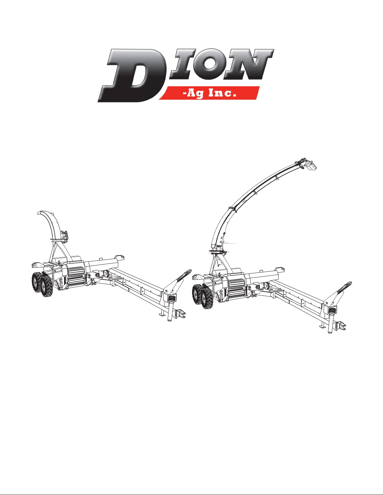
Dion-Ag F41 Bedienungsanleitung

Operator’s Manual
Forage Harvester
Manual No. F4117E987E V1.1

2
DION-AG INC. LIMITED WARRANTY TERMS AND CONDITIONS
Covered by Warranty – Under the warranty, Dion-Ag guarantees its new machinery and/or equipment to be free
of defects, both in workmanship and material, for a period of one (1) year from the time of delivery by the dealer.
Dion-Ag Inc. will repair or replace, at its discretion and without charge for service parts or labour, any defective part
of the equipment on condition that the machinery and/or equipment has been operated in accordance with the in-
structions contained in the Dion-Ag Inc. Operator’s Manual.
Not covered by Warranty – This warranty does not cover: (1) service parts and labour needed to maintain the
unit; and (2) the replacement of parts due to normal wear and tear. The owner is responsible for these items. Some
examples of maintenance and normal wear parts are: oil, lubricants & other uids, belts, knives, clutch and clutch
discs, roller chain, paddles, etc. Dion-Ag Inc. is not responsible for depreciation or damage caused by normal wear,
lack of reasonable and proper maintenance, failure to follow operating instructions, misuse, lack of proper protec-
tion during storage, vandalism, the elements, collision or accident.
Securing Warranty Service – To secure warranty service, the purchaser must report the machinery and/or equip-
ment defect to an authorized dealer and request warranty service within the applicable warranty terms.
Owner’s Obligation – It is the responsibility of the Owner to transport the equipment to the service shop of an au-
thorized Dion-Ag Dealer or to reimburse the dealer for any travel or transportation expense involved in fullling this
warranty. This warranty does NOT cover rental of replacement equipment during the repair period, loss of prots,
or other coercial loss, and any or all incidental or consequential damages, overtime labour charges and/or freight
charges for replacement parts.
Limitations of This Warranty – No agent, employee or representative of Dion-Ag Inc. has the authority to amend,
or modify, in any manner whatsoever, the terms of the present warranty. The express warranties herein contained
exclude all other express, implied or statutory warranties. THIS WARRANTY IS IN LIEU OF ALL OTHER WAR-
RANTIES INCLUDING THE WARRANTIES OF MERCHANTABILITY AND/OR FITNESS FOR ANY PARTICULAR
PURPOSE.
Right to Inspect – Dion-Ag and its authorized agents reserve the right to inspect the purchaser’s Dion-Ag product
to determine if a defect in material or workmanship exists prior the coencement of any covered repairs. It is the pur-
chaser’s responsibility to ensure availability and/or delivery of the product to Dion-Ag for the purpose of inspection.
Right to Make Design Changes – Dion-ag reserves the right to make changes in the design and other changes in
its products at any time and from time to time without notice and without incurring any obligation of its part to modify,
improve or add to products previously ordered from Dion-Ag and sold or shipped by Dion-Ag.
Liability – Dion-Ag Inc. shall not be liable, if, during the use of the machinery and/or attachment, the security guards
have been removed, modied, or have not been properly maintained.
The Warranty shall not apply if the instructions mentioned in this manual have not been followed completely and
correctly. Nor will the warranty apply if the owner or any third party modies the machine without Dion-AG’s know-
ledge and/or authorization. Every purchaser, when buying a Dion-Ag machine, agrees and undertakes to use and
operate the machinery and its component parts safely, and in accordance with all applicable laws, and in accord-
ance with the Operator’s Manual. Furthermore, the purchaser agrees and accepts to indemnify and hold harmless
Dion-Ag for all losses and damages to any person or property resulting from the purchaser’s non-compliance with
the terms and conditions of this warranty. Each purchaser further agrees to bring the warranty to the attention of any
subsequent purchaser, and to obtain agreement therein as a condition of resale or transfer.
Manual No. F4117E987E V1.1

3
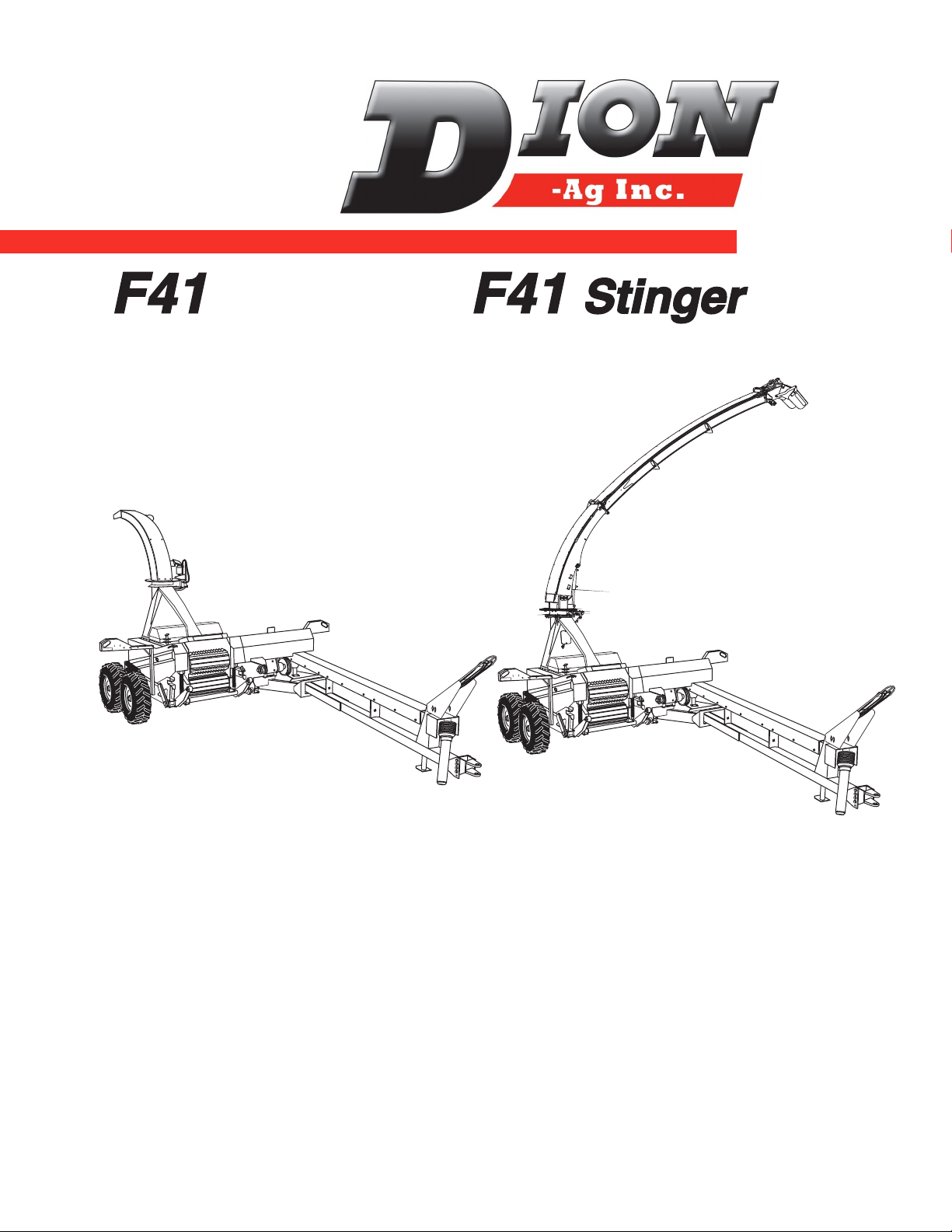
Forage Harvester F41 & F41 Stinger
TO OUR CUSTOMER
We appreciate your condence in Dion Farm Equipment and thank you for your trust. In preparing this
manual, we hope we have furnished you with a valuable tool for operating and maintaining this ne ma-
chine. Use this manual as your guide. Practicing the instructions given here will result in many years of
dependable service from your machine.
Your dealer can give you assistance with parts and specially trained personnel to assist you in repair and
maintenance.
Call your dealer if you need any assistance or information.
Manual No. F4117E987E V1.1

4
SPECIFICATIONS.....................................................................................................................8
SERIAL NUMBER LOCATION ................................................................................................. 9
CHECK LIST............................................................................................................................. 10
PRE-SEASON CHECKS.....................................................................................................................10
DAILY CHECKS ..................................................................................................................................11
FOREWORD .............................................................................................................................12
TO OUR CUSTOMER.........................................................................................................................12
THIS MANUAL SHOULD REMAIN WITH THE MACHINE WHEN SOLD...........................................12
WARRANTY INFORMATION..............................................................................................................12
WARRANTY ON THE METAL DETECTOR ........................................................................................12
SAFETY ..............................................................................................................................................12
SAFETY RULES .......................................................................................................................13
SAFETY ALERT SYMBOL ..................................................................................................................13
DANGER, WARNING AND CAUTION ................................................................................................13
DECALS:.............................................................................................................................................13
FOLLOW A SAFETY PROGRAM........................................................................................................13
A WORD TO THE OPERATOR...........................................................................................................13
PTO OPERATION ...............................................................................................................................15
MANDATORY STOPPING PROCEDURE ..........................................................................................15
GUARDS AND SHIELDS ....................................................................................................................16
SAFETY SIGN LOCATION ....................................................................................................... 17
SAFETY SIGN APPLICATION PROCEDURE ...................................................................................21
MATERIAL SUPPLIED SEPARATELY WITH THE MACHINE: ...........................................................22
HARVESTERS ARE SHIPPED TO OPERATE AS FOLLOWS:..........................................................22
OPTIONAL EQUIPMENT CHOICES:..................................................................................................22
DELIVERY.................................................................................................................................22
MANUAL JACK ...................................................................................................................................23
RECEIVING YOUR FORAGE HARVESTER ......................................................................................23
PREPARING THE FORAGE HARVESTER ........................................................................................23
ASSEMBLING INSTRUCTIONS............................................................................................... 23
INSTALLING THE CONTROL BOX ....................................................................................................24
INSTALLING THE CONTROL BOX (F41 STINGER MODEL ONLY)..................................................24
CONNECTING THE POWER-TAKE-OFF (PTO) ...............................................................................26
INSTALLING THE FOLDABLE SPOUT (F41 MODEL ONLY).............................................................27
INSTALLING THE 12” (30 cm) SPOUT EXTENSION (F41 MODEL ONLY) FIGURE 12....................28
INSTALLING THE 24” (60 CM) SPOUT EXTENSION (F41 MODEL ONLY) ......................................29
HOW TO MAKE THE ELECTRICAL CONNECTIONS ON THE SPOUT (F41 MODEL ONLY)..........31
INSTALLING THE CLOSING PLATE ON THE SPOUT ......................................................................32
INSTALLING MUDGUARDS OVER TANDEM WHEELS ...................................................................32
INSTALLING AN ATTACHMENT ON THE FORAGE HARVESTER ..................................................33
INSTALLING THE RECUTTER BAR ASSEMBLY FOR CORN CROP ..............................................35
INSTALLING THE GRAIN PAN AND FRONT RUBBER PAD ASSEMBLY FOR CORN CROP..........35
INSTALLING A LIGHT ON THE SPOUT DEFLECTOR (F41 MODEL ONLY) ....................................36
INSTALLING THE INSPECTION LIGHT ............................................................................................37
ASSEMBLING INSTRUCTIONS - LIQUID INCORPORATION SYSTEM ................................ 38
INSTALLING A SECOND TANK..........................................................................................................47
ASSEMBLING INSTRUCTIONS - MANUAL QUICK-DISCONNECT HITCH .......................... 50
ASSEMBLING INSTRUCTIONS - ELECTRIC QUICK-DISCONNECT HITCH (UP TO 2017) 52
ASSEMBLING INSTRUCTIONS - ELECTRIC QUICK-DISCONNECT HITCH (2017+) .......... 54
ASSEMBLING INSTRUCTIONS - DRAW BAR EXTENSION.................................................. 58
ASSEMBLING INSTRUCTIONS - TRANSPORT LIGHTS....................................................... 60
TABLE OF CONTENTS
Manual No. F4117E987E V1.1

5
CORN CRACKER INSTALLATION INSTRUCTIONS .............................................................. 61
PARTIAL DISMANTLING OF THE CORN CRACKER FOR HAY CROP ................................ 76
PARTIAL REASSEMBLING OF THE CORN CRACKER FOR CORN CROP......................... 83
HYDRAULIC SPOUT CONVERSION ...................................................................................... 88
BREAK-IN SPEED ..............................................................................................................................88
BOLT TORQUE SPECIFICATIONS ....................................................................................................88
METAL DETECTOR............................................................................................................................88
STOPPING THE MACHINE ................................................................................................................88
TRANSPORTATION ON PUBLIC ROADS .........................................................................................88
OPERATING INSTRUCTIONS ................................................................................................. 90
TRANSPORT POSITION - F41 STINGER..........................................................................................91
PREPARING FOR FIELD OPERATION..............................................................................................92
HITCHING THE FORAGE HARVESTER TO THE TRACTOR .........................................................92
ADJUSTING THE ATTACHMENT GROUND CLEARANCE..............................................................93
STARTING UP.....................................................................................................................................93
INFORMATION ON THE METAL DETECTOR....................................................................................94
DAILY CHECKS ON THE METAL DETECTOR ..................................................................................94
INITIALIZING THE METAL DETECTOR
(STARTING UP THE MACHINE WITH METAL DETECTOR) ............................................................95
STOPPING THE MACHINE ................................................................................................................95
STARTING OPERATION.....................................................................................................................96
THE CONTROL BOX .........................................................................................................................96
EMERGENCY STOP ..........................................................................................................................96
OPERATING INSTRUCTION FOR THE F41 STINGER SPOUT .......................................................96
WHAT TO DO WHEN THE MACHINE DETECTS A FERROUS METAL............................................97
WHAT TO DO IF MATERIAL ACCUMULATION OCCURS (CLOGGING) ..........................................98
HOW TO BY-PASS THE METAL DETECTOR ...................................................................................99
SHEAR BOLT .....................................................................................................................................100
PRESSURE AND FLOW CHARTS FOR STANDARD NOZZLE.........................................................101
STANDARD NOZZLE FOR WATER SPRAYING TEEJET XR8004VS ...............................................101
HOW TO OPERATE THE LIQUID INCORPORATION SYSTEM........................................................101
CALIBRATION PROCEDURES .........................................................................................................101
PRESSURE ADJUSTMENT ...............................................................................................................101
DETECTION SYSTEM FOR SAFETY BOLT BREAKAGE OR
FRICTION CLUTCH SLIPPAGE ON THE CUTTER HEAD TRANSMISSION SHAFT. ......................102
TRANSPORT LIGHT ..........................................................................................................................103
HYDRAULIC CIRCUIT........................................................................................................................104
POWER-TAKE-OFF (PTO) .................................................................................................................104
LUBRICATION CHART .......................................................................................................................104
CHAINS LUBRICATION......................................................................................................................104
GEAR BOX LUBRICATION.................................................................................................................104
LUBRICATION .......................................................................................................................... 104
CORN CRACKER LUBRICATION ......................................................................................................111
ADJUSTMENTS - MAINTENANCE.......................................................................................... 113
WHEEL POSITIONING ......................................................................................................................113
GROUND CLEARANCE .....................................................................................................................114
DISMANTLING AND REASSEMBLY OF THE POWER-TAKE-OFF (PTO) ROTATING GUARDS.....114
FORAGE HARVESTER DRAW BAR..................................................................................................115
FEED ROLL BALANCING SPRINGS ................................................................................................115
UPPER FEED ROLL CHAIN TENSION .............................................................................................116
LOWER FEED ROLL CHAIN TENSION ............................................................................................116
STRAW CHOPPING ...........................................................................................................................116
BALANCING SPRINGS 2 ...................................................................................................................117
UPPER ROLL ADJUSTING BOLTS ...................................................................................................118
TABLE OF CONTENTS
Manual No. F4117E987E V1.1

6
MAGNETIC DRAIN PLUGS................................................................................................................118
SPOUT WEAR PLATE (F41) ..............................................................................................................119
SPOUT WEAR PLATE (F41
STINGER
) .............................................................................................119
HYDRAULIC SPOUT CYLINDER STROKE ADJUSTMENT (F41 STINGER) ...................................120
ADJUSTING THE FREE ROTATION OF THE SPOUT ......................................................................121
ROTATION MOTOR ADJUSTMENT (F41 STINGER) .......................................................................122
FEED ROLL STOPPING SYSTEM ....................................................................................................123
FAN BELT TENSION .........................................................................................................................124
FAN AND TRANSMISSION BELT REPLACEMENT ..........................................................................124
CORN CRACKER BELT TENSION ....................................................................................................125
CORN CRACKER BELT REPLACEMENT .........................................................................................126
TRANSMISSION BOX BELTS ............................................................................................................127
REVERSE, NEUTRAL AND FORWARD SPEEDS POSITIONS ........................................................127
ANGLE DRIVE TRANSMISSION BOX SHEAVE ...............................................................................128
FAN ADJUSTMENT ...........................................................................................................................129
KNIFE ADJUSTMENT ........................................................................................................................131
KNIFE GRINDING ..............................................................................................................................132
KNIFE REPLACEMENT .....................................................................................................................134
KNIVES & SHEAR BAR GENERAL INFORMATION..........................................................................134
SHEAR BAR ADJUSTMENT ..............................................................................................................135
DAILY ADJUSTMENT (AFTER KNIVES HAVE BEEN GROUND)......................................................135
REPLACEMENT AND INITIAL ADJUSTMENT OF THE SHEAR BAR .............................................136
CUTTING LENGTH SELECTION .......................................................................................................137
PROCEDURE FOR CHANGING THE CUTTING LENGTH ...............................................................138
PROCEDURE TO INCREASE THE FORAGE HARVESTER’S FEEDING SPEED BY 33% .............139
SMOOTH FEED ROLL CLEANER ADJUSTMENT.............................................................................140
MAINTENANCE PROCEDURE FOR THE CUTTER HEAD BOTTOM PLATE ASSEMBLY ..............141
MAINTENANCE PROCEDURE FOR THE FAN BOTTOM PLATE ASSEMBLY .................................142
CORN CRACKER SHEAVE ALIGNMENT .........................................................................................144
CORN CRACKER Q.D. BUSHINGS ..................................................................................................155
CORN CRACKER LOWER ROLL BEARINGS ...................................................................................145
CORN CRACKER UPPER ROLL BEARINGS ...................................................................................147
CORN CRACKER LOWER ROLL HALF BOTTOM PLATE ...............................................................149
CORN CRACKER ROLL SCRAPER .................................................................................................151
UPPER CORN CRACKER ROLL “ZERO” POSITION ADJUSTMENT .............................................152
UPPER CRACKER ROLL PRESSURE AND GAP ADJUSTMENT ....................................................153
CORN CRACKER INITIAL START UP ADJUSTMENT ......................................................................154
LIFTING THE ATTACHMENT .............................................................................................................154
LIFTING ARMS ..................................................................................................................................154
STONE CARRIAGE ADJUSTMENT ...................................................................................................155
STONE REPLACEMENT....................................................................................................................155
CUTTER HEAD SENSOR ADJUSTMENT..........................................................................................156
FEED ROLL SHAFT SENSOR ADJUSTMENT...................................................................................156
PTO FRICTION CLUTCH ADJUSTMENT (OPTION) .........................................................................157
VENTING THE CLUTCH.....................................................................................................................158
CLUTCH DISMANTLING PROCEDURE ............................................................................................159
CLUTCH ASSEMBLING PROCEDURE..............................................................................................160
CLUTCH TORQUE SETTING ............................................................................................................161
TRANSMISSION CLUTCH LEVER POSITION SENSOR .................................................................162
DISASSEMBLING AND ASSEMBLING THE RADIAL PIN CLUTCH (TORQUE LIMITER)................163
AT THE END OF THE SEASON, IT IS RECOENDED TO PROCEED AS FOLLOWS:......................167
METAL DETECTOR DIAGNOSTIC SHORT PROCEDURE..................................................... 168
«LED» DISPLAY ON METAL DETECTOR............................................................................... 169
JUMPER POSITION ................................................................................................................. 169
TROUBLESHOOTING.............................................................................................................. 170
TABLE OF CONTENTS
Manual No. F4117E987E V1.1

7
Specications and design are subject to change without notice
and without liability therefore.
WEIGHT (with 1100X16 tires)
with metal detector .................................................................................... 5280 lbs (2400 Kg)
without metal detector ............................................................................... 5230 lbs (2380 Kg)
DIMENSIONS
Overall width
With 31x13.50 - 15 Terra Rib tires. 142” (361cm) - Narrow tandem 130” (330 cm)
With 31x15.50 - 15 Terra Grip tires 150” (381cm) - Narrow tandem 138” (350 cm)
Length..........................................................................................................228” (579 cm)
Height ..........................................................................................................129” (328 cm)
Minimum height - F41 Stinger ....................................................................120” (305 cm)
Maximum height - F41 Stinger ....................................................................222” (565 cm)
Spout turning radius - F41 Stinger...............................................................200” (508 cm)
ANGLE DRIVE TRANSMISSION
540 or 1000 RPM (buyer’s choice)
MAIN TRANSMISSION
3 speed transmission with overload clutch
3 lengths of cut
OPERATING CAPACITY
540 RPM to 730 RPM - 90 to 135 HP
1000 RPM to 815 RPM - 90 to 180 HP
1000 RPM to 1033 RPM - 160 to 300 HP
ELECTRICAL CONTROLS
Transmission
Spout (230˚ rotation)
Deector
CUTTER HEAD
12 helicoidal knives (or 8 knives - buyer’s choice)
24” (61 cm) wide
22” (56 cm) diameter
speed: 815 or 1033 RPM
SINGLE TIRES AND WHEELS
1100 X 16 - 8 ply DYNA RIB
16.5 X 16.1 - 8 ply DYNA RIB
TANDEM TIRES AND WHEELS
31x13.50 - 15 Terra Rib
31x15.50 - 15 Hippo
29x10.5-15 - Trac Chief
SPECIFICATIONS
Manual No. F4117E987E V1.1

8
Specications and design are subject to change without notice
and without liability therefore.
STANDARD EQUIPMENT
Hydraulic lift control
Hydraulic tongue control
Cutting edges of the cylinder knives with tungsten carbide treatment
Built-in grinder
Transmission, spout and deector electrical controls
Double sprocket wheel for lengths of cut: 26 teeth for 3/8” (9.5 ) standard upon delivery
and 34 teeth for 1/2” (13 )
Shear bar adjustment on one side
F41: 240orotation spout
F41 Stinger: 310orotation spout
OPTIONAL EQUIPMENT
8 or 12 knife cutter head
Metal detector (standard on F41 Stinger model)
Spout extension (12” or 24”) (30 or 60 cm) (F41 model only)
Single wheels or tandem wheels
Double sprocket wheels for lengths of cut: 17 teeth for 1/4” (6.35 )
Deector light
Inspection light
Manual (cord) quick-disconnect hitch
Electrical heavy-duty quick-disconnect hitch (N/A on F41 Stinger model)
Liquid incorporation system
Extra tank for liquid incorporation system
Recuperation grain pan
Recuter bar (for corn only)
Corn Cracker
Draw Bar Hooker
Draw Bar Extension
Detection system for safety bolt breakage
System to increase Forage Harvester’s feeding speed by 33%
OIL CAPACITY
Angle drive transmission: 1.8 imperial gallons - 2.0 US gallons - 8 liters
Main transmission: 0.88 imperial gallon - 1.1 US gallons - 4 liters
SPECIFICATIONS
Manual No. F4117E987E V1.1

9
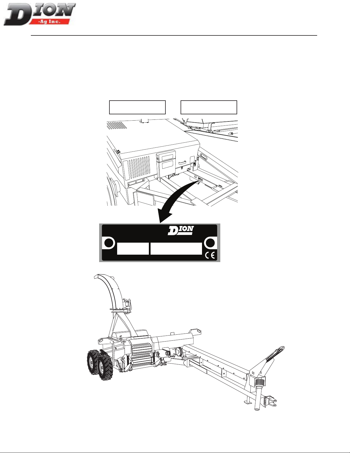
For your convenience, write down in full in this manual both the model and serial numbers of your ma-
chine, as shown on the name plate illustrated below. Always mention both the model and the serial num-
bers when ordering parts or regarding any other correspondence referring to your machine.
Write down your number here:
MODEL NO. SERIAL NUMBER
SERIAL NUMBER LOCATION
MADE IN CANADA
DION-AG INC.
BOISBRIAND QUE.
MODEL NO.
SERIAL NO.
Dion-Ag Inc.
DFE
MADEIN CANADA
D.F.E.INC.
BOISBRIANDQUE.
MODELNO.
SERIALNO.
PAR/BY
REAR
RIGHT
LEFT
FRONT
Manual No. F4117E987E V1.1

10
PRE-SEASON CHECKS
Check condition of knives and shearbar. Check that knives and shearbar are set at zero
clearance.
Check tension of belts and chains. Make sure sheaves and sprockets are correctly
aligned.
Check all adjustable components for correct setting. Make sure adjustments are
correctly done (fan, etc)
Check tire pressure. See specications.
Check wheel rim bolt torque. See Specications.
Perform complete lubrication and servicing of the machine. Make sure all grease ttings
are in place and taking grease properly. Check gearbox and transmission uid levels.
Look for loose or missing bolts and parts.
Run the machine in a stationary position at half-speed for a short period of time.
Shut off tractor engine. Make sure all moving parts have stopped, then inspect
bearings for over-heating, excessive wear, or loose anges and lock collars.
Check metal detection system for proper operation (if installed on machine). Always
service metal detector when tractor engine is switched off.
Make sure the proper operating adjustments have been made for current crop
conditions.
Make sure SMV emblem (Slow Moving Vehicle) is in good condition and visible.
Make sure all safety shields are installed. Review Safety Precautions.
Check parts for wear (paddles, fan bottom, spout liner, etc.).
CHECK LIST
Manual No. F4117E987E V1.1
Andere Handbücher für F41
1
Dieses Handbuch passt für folgende Modelle
1
Inhaltsverzeichnis
Andere Dion-Ag Landwirtschaftliche Geräte Handbücher