EIJKELKAMP QUICK DRAW 2900F1 Bedienungsanleitung

INSTRUCTIONS
OPERATING
Model 2900F1 “QUICK DRAW” SOILMOISTURE PROBE December 2009
The 14.04.05 QuickDraw Soilmoisture Probe is the most effective portable moisture measuring
instrument available. Designed for rugged eld use, the patented construction utilizing capil-
lary tube connections and a super porous ceramic tip assures fast response and accurate
readings, independent of temperature differences. The self-servicing feature, unique in tensi-
ometer construction, eliminates the need for accessory service kits, and assures fast response
times after years of use.
The Probe is shipped in a dry condition for greater convenience in handling and storage over a
period of time. Follow the simple instructions to water ll your unit in preparation for use.
(Figure 1) - 14.04.05 Soilmoisture "Quick Draw" Probe
P.O. Box 4, 6987 ZG Giesbeek
Nijverheidsstraat 30,
6987 EM Giesbeek,
The Netherlands
T+31 313 880200
F+31 313 880299
Ihttp://www.eijkelkamp.com
M1.14.04.05.E
14.04.05

2
TABLE OF CONTENTS
Table of Contents.................................................................................................Page 2
Unpacking............................................................................................................Page 3
Cautions & Warnings...........................................................................................Page 3
Warranty & Liability..............................................................................,,,.............Page 3
Aquaint Yourself With The Parts..........................................................................Page 4
Theory of Operation............................................................................................Page 5
Venting and Adjusting Dial Gauge.......................................................................Page 6
Requirements Prior to Use / Initial Filling............................................................Page 7
Installation...........................................................................................................Page 11
Making a Soil Moisture Measurement.....................................................Page 11
Dial Gauge Pressure Build-up.................................................................Page 14
Irrigation Schedualing.............................................................................Page 15
Routine Measurements...........................................................................Page 16
Troubleshooting..................................................................................................Page 17
Replacing the Ceramic Tip..................................................................................Page 18
Replacing the Dial Gauge...................................................................................Page 20
Time Required to make a Reading.....................................................................Page 22
Tips for Scheduling Irrigations............................................................................Page 23
Care and Maintenance.......................................................................................Page 25
Parts List.............................................................................................................Page 27

Eijkelkamp Agrisearch Equipment (EAE)warrants all products manufactured by EAE to be free from
defects in materials and workmanship under normal use and service for twelve (12) months
from the date of invoice provided the section below has been met.
Eijkelkamp (EAE) is not liable for any damages, actual or inferred, caused
by misuse or improper handling of its products. EAE products are designed to be used solely as
describedintheseproduct operatinginstructionsbyaprudentindividual under normaloperating
conditions in applications intended for use by this product.
WARRANTY & LIABILITY
UNPACKING
CAUTIONS & WARNINGS
The Soilmoisture "Quick Draw" Probe should be removed from the eld prior to the onset
of freezing conditions. Since the Probe is a water-lled system, it is essential that the unit
be stored and used at temperatures above freezing. Freezing temperatures, of course, will
cause the water within the unit to freeze and expand as ice is formed. This can cause break-
age of the ceramic tip and distort or rupture the thin-walled Bourdon tube within the dial
gauge.
If the Bourdon tube is ruptured, the dial gauge cannot be repaired and will have to be replaced.
If the Bourdon tube is distorted but not ruptured, it may be possible to reset the pointer on the
gauge to correct the change in calibration caused by freezing.
Intense heat can cause the plastic Carrying Case to distort and can result in the evaporation
of all water from the sponge within the Carrying Case. This will be detrimental to the opera-
tion of the Soilmoisture Probe. It will also result in frequent servicing for removal of air. Do
not subject the Soilmoisture Probe to intense heat while storing or transporting it. Very high
temperatures can develop within a closed cab of a truck or the trunk of a car.
Please see page for care and user tips.
Not Liable for improper use. Remove all packing materials and check the 2900F1 Soilmois-
ture "Quick Draw" Probe for any damage that may have occurred during shipment. If any
part of the Quick Draw is damaged, call the carrier immediately to report it. Keep the ship-
ping container and all evidence to support your claim.
Do not bump or drop the dial gauge or ceramic sensing tip or they could break and will need
to be replaced. Take care not to let the sensing tip come in contact with grease or any other
similar material that could clog the pores of the ceramic.
Please verify that your shipment is complete.
3

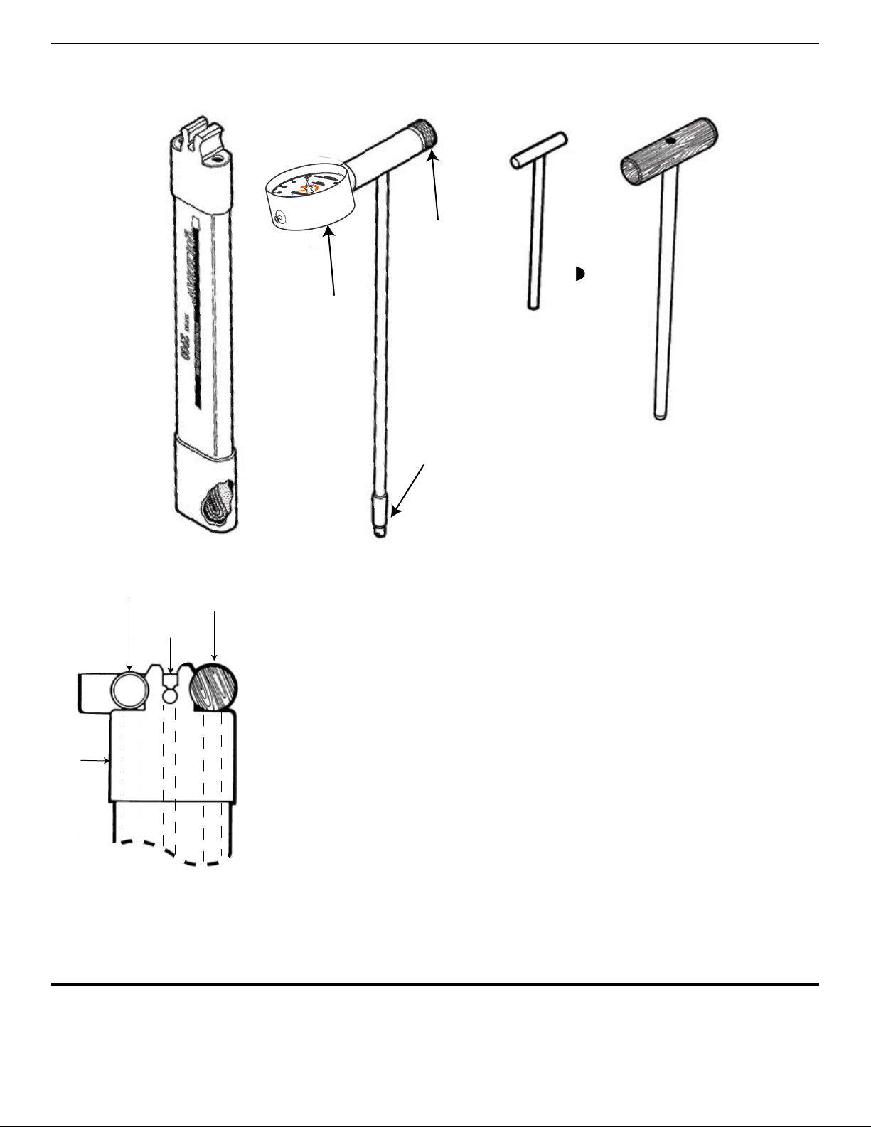
(Figure 2) - 2900K1 Parts
AQUAINT YOURSELF WITH THE PARTS
The Probe, Coring Tool, and Cleaning Rod are held in place by the molded plas-
tic retainers at the top of the Carrying Case.
NOTE: The Probe ts into the side of the Carrying Case that is marked “PROBE”
, and the Coring Tool ts into the other side of the Carrying Case that is marked
“CORING TOOL”. (Fig. 3).
It is very important to keep the Probe in the side of the Carrying Case marked
“PROBE” when it is not actually being inserted in the soil, because this side of
the Carrying Case has a water storage reservoir at the bottom. During the “Initial
Filling” operation, pictured and described on pages 7 through 10, you will ll
the water storage reservoir. Thereafter, the sensing tip of the Probe will be kept
moist.
An Accessory Kit is provided with each Probe. It consists of a small screwdriver,
a 3/32” Allen wrench, and a replacement sensing tip and seals. The screwdriver
is used to vent and adjust the dial gauge and to replace the sensing tip. TheAllen
wrench is used in the event the dial gauge needs replacement.
PROBE CORING
TOOL
CLEANING
ROD
PROBE
CASE
(Figure 3) - Probe case
Tool placement
DIAL GAUGE
NULL KNOB
POROUS CERAMIC
SENSING TIP
CLEANING RODCARRYING CASE PROBE CORING TOOL
4

55
THEORY OF OPERATION
The 14.04.05 Soilmoisture Probe is a tensiometer-type instrument that reads
soil suction directly. The “soil suction” reading is a direct measure of the availability
of moisture for plant growth, and the standard unit of measurement is the “bar”. The
bar* is a unit of pressure in the metric system and is used to dene positive pressure
(above atmospheric pressure), or negative pressure or vacuum (below atmospheric
pressure).
The gauge on the Probe is calibrated in hundredths of a bar (or centibars) of vacuum,
and is graduated from zero to 100.
In scientic work, it is becoming customary to express pressures and vacu-ums in a
unit of measure called a “Pascal”, and a “Kilopascal”, which is 1000 times as large as
a Pascal. A “centibar”, as used above, is exactly equal to a Kilopascal. Therefore, the
dial gauge on the Probe also reads in kilopascals and is graduated from zero to 100
kilopascals (KPa).
Soil suction is actually created by the attraction that each soil particle has for the
water in the soil. Because of this attraction, water forms a lm around each particle of
soil and collects in the capillary spaces between the soil particles. As the soil be-
comes drier, these lms become thinner and the attraction or soil suction increases.
The plant root has to over-come this soil suction, or attraction force, in order to
withdraw moisture from the soil. The measurement of soil suction then gives a direct
indication of the amount of work the plant root must do to get water from the soil. The
only moisture measuring instruments that accurately measure soil suction are those
using the tensiometer principle. These instruments read centibars of soil suction
directly without calibration for soil type, salinity, or temperature.
When the Probe is inserted into the cored hole, there are various effects associated
with the movement of the porous ceramic sensing tip through the soil. The soil sur-
rounding the tip is slightly compacted and the wiping action of the porous ceramic
through the soil causes small thermal effects. It takes a few moments for these dis-
turbances to disperse, and this is the reason that it is not desirable to move the Null
Knob for the rst minute after insertion of the Probe.
In order to obtain a soil suction reading, it is necessary for a small amount of water
to transfer between the sensing tip of the Probe and the soil. When the Null Knob is
turned clockwise, water is forced out of the Probe sensing tip and into the surround-
ing soil. When the Null Knob is turned counterclockwise, a vacuum is created within
the Probe, which causes moisture to move from the soil through the ceramic sens-
ing tip and into the Probe. In order to obtain an accurate reading within the minimum
amount of time, one must be careful not to disturb the moisture conditions surround-
ing the sensing tip.
Steps for initial filling
(before installation)
When examining the Probe, DO NOT leave the porous ceramic sensing tip exposed
to the air for prolonged periods. When the Probe is removed from the Carrying Case
and the sensing tip is not kept moist, evaporation of moisture from the tip will pull the
dial gauge up to a very high centibar reading. Under these conditions, air can dif-
fuse through the water in the pores of the sensing tip and enter the Probe, which can
result in a decrease in sensitivity and require a relling cycle.

Venting and Adjusting the Dial Gauge
The 2060FG dial gauge is hermetically sealed at the factory at sea level.
If you live at a higher elevation, the pointer on the dial gauge may read
higher than zero when you unpack it. This is due to the lower atmospheric
pressure at your elevation.
First, simply press the vent pin located, at the top of the gauge, to release
any collected air. Located on the face of the gage is an insertion point for
a small athead screwdriver. If the gauge is reading high, turn the screw-
driver clockwise an estimated amount to correct the error. If the gauge
reads low, turn the screwdriver counterclockwise an estimated amount to
correct the error. Repeat the process if necessary until the pointer is on
zero.
VENT PIN
EFFECTS OF ALTITUDE ON OPERATION OF THE PROBE
PRACTICAL READING RANGE
0 TO 85 CENTIBARS
IN THIS RANGE AIR COMING
OUT OF SOLUTION MAKES
READING INACURATE
THEORETICAL LIMIT
OF READING
AT SEA LEVEL
PRACTICAL READING RANGE
0 TO 81 CENTIBARS
IN THIS RANGE AIR COMING
OUT OF SOLUTION MAKES
READING INACURATE
THEORETICAL LIMIT
OF READING
IN THIS RANGE WATER
BREAKS INTO A VAPOR
CAUSING UNIT TO LOOSE
ALL OF ITS WATER
AT 1000 FT.
ABOVE SEA LEVEL
CENTIBARS OF SOIL
SUCTION
SOILMOISTURE EQUIPMENT CORP
Santa Barbara, CA USA
90
80
70 60 50 40
30
20
10
0
DRY
WET
100
D
O
N
O
T
F
R
E
E
Z
E
40*-.0*4563&
CENTIBARS OF SOIL
SUCTION
SOILMOISTURE EQUIPMENT CORP
Santa Barbara, CA USA
90
80
70 60 50 40
30
20
10
0
DRY
WET
100
D
O
N
O
T
F
R
E
E
Z
E
40*-.0*4563&
AT 5000 FT.
ABOVE SEA LEVEL
CENTIBARS OF SOIL
SUCTION
SOILMOISTURE EQUIPMENT CORP
Santa Barbara, CA USA
90
80
70 60 50 40
30
20
10
0
DRY
WET
100
D
O
N
O
T
F
R
E
E
Z
E
40*-.0*4563&
PRACTICAL READING RANGE
0 TO 68 CENTIBARS
IN THIS RANGE AIR COMING
OUT OF SOLUTION MAKES
READING INACURATE
THEORETICAL LIMIT
OF READING
IN THIS RANGE WATER
BREAKS INTO A VAPOR
CAUSING UNIT TO LOOSE
ALL OF ITS WATER
The Reading Range is Reduced Approximately 3.5 Centibars
for Each 1000 Ft. Increase in Elevation
(Figure 4) - Venting the gauge
(Figure 5) - Effects of Altitude
6

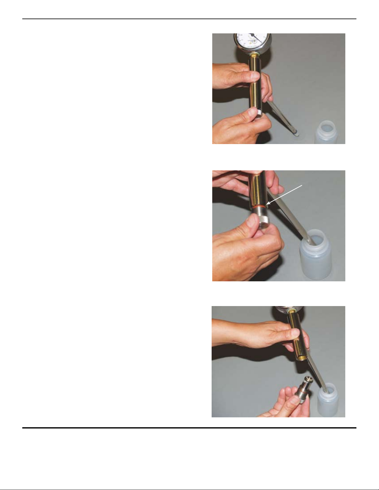
STEP 1
Turn Null Knob clockwise as far as it will go and then
insert the porous ceramic sensing tip in water.
STEP 2
Keep the sensing tip in water. Turn the Null Knob coun-
terclockwise until you just see the red ring.
On initial lling, the pointer will normally rise to a reading
of 40 to 50. Let the pointer drop to zero.
STEP 3
Keep the sensing tip in water. Continue to turn the Null
Knob slowly counterclockwise until it is loose and can be
removed.
REQUIREMENTS PRIOR TO USE / INITIAL FILLING
RED RING
(Figure 8)
(Figure 7)
(Figure 6)
7

STEP 4
Fill the handle with water. A teaspoon works well for this
operation. Water should be poured into the handle slowly
and carefully so that air bubbles are not trapped. If you
see a bubble clinging to the smooth wall or bottom of the
handle cavity, nudge it free with the sharp end of a pencil.
STEP 5
Screw the Null Knob completely back in the Handle, which
will push out excess water.
While you are doing this, water will ooze out through the
porous ceramic tip and drip off the end.
STEP 6
Turn the Null Knob clockwise as far as it will go.
REQUIREMENTS PRIOR TO USE / INITIAL FILLING (cont.)
(Figure 10)
(Figure 11)
(Figure 9)
8

STEP 7
Remove the tip from the water and dry it with Kleenex or simi-
lar absorbent tissue. The dial pointer will rise to a reading of
20 or 30 as moisture is pulled into the dry tissue.
STEP 8
Turn the Null Knob counterclockwise until you just see the
red ring. The pointer will normally rise to a reading of 80 or
90 centibars if you live at an elevation between sea level and
about 2000 ft. If you live at higher elevations, the maximum
reading will be somewhat lower. See page 14, which de-
scribes the effect of altitude on the operation of the Probe.
If the pointer does not rise it can mean that rough handling
has cracked the porous ceramic sensing tip. See section on
“Care and Maintenance” for corrective action.
STEP 9
Immerse the porous sensing tip again in water and wait until
the pointer drops to zero.
REQUIREMENTS PRIOR TO USE / INITIAL FILLING (cont.)
RED RING
(Figure 13)
(Figure 12)
(Figure 14)
9

STEP 10
Repeat Step 3, removing the Null Knob again while the sensing tip is in the
water. Repeat Steps 4, 5, and 6, again relling the handle with water. Insert
the Null Knob and turn it clockwise as far as it will go.
STEP 11
Check Response Time. To do this, wipe the Probe and porous ceramic tip
with absorbent tissue to remove all excess water. Turn the Null Knob until
the pointer reaches a reading of 50 on the dial. Now when you dip the sens-
ing tip in the water, the pointer will normally drop from a reading of 50 to 10
in approximately one second - the time that it takes to say “one, one thou-
sand”. The Probe is ready for use if the response time is approximately one
second.
STEP 12
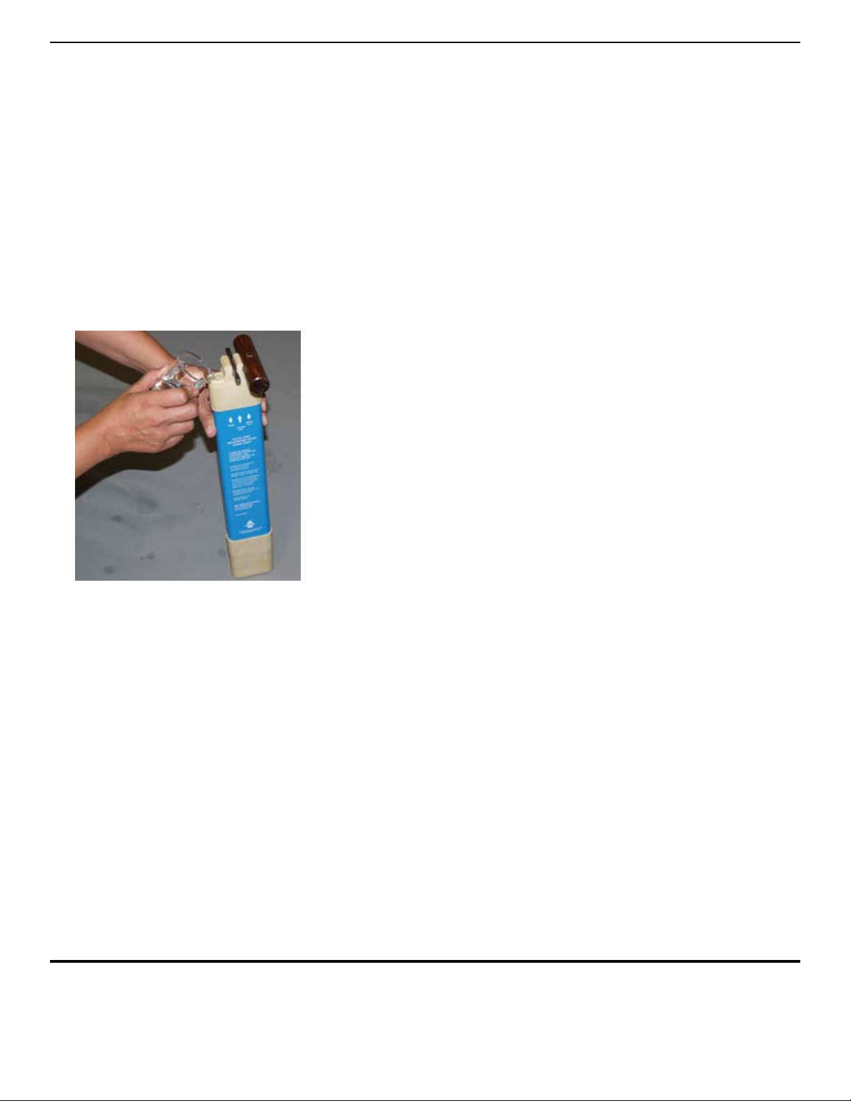
Fill the Carrying Case tube, which is labeled “PROBE” with water and allow
it to stand for a minute or two (See Fig.15). This will ll the sponge cartridge
with water. Empty out excess water and insert the Probe. The sponge car-
tridge in the Carrying Case will now keep the porous ceramic sensing tip wet
so it is ready to use at any time in the eld. In the future, always keep the
Probe in the Carrying Case when not in use.
REQUIREMENTS PRIOR TO USE / INITIAL FILLING (cont.)
After initial lling, if the response time is considerably more than one second, it
usually indicates that an air bubble has been trapped in the handle. To correct this,
simply repeat Steps 8 and 9, then Steps 3, 4, 5, and 6. Again look into the handle
cavity after lling to see if there are any bubbles clinging to the internal wall. In the
event there are bubbles, simply nudge them loose with the sharp end of a pencil. Fill
the cavity in the handle to the top, replace the Null Knob, wipe it dry, and again check
the response time.
The pointer may have to be adjusted after the lling operation. First read the following
section concerning the Dial Gauge and then refer to the “Venting and Adjusting the
Dial Gauge” section for specic instructions for adjusting the dial gauge pointer.
When the Probe is in the Carrying Case and is held vertically, the pointer on the
dial gauge should read zero. You will note, however, that if the Carrying Case is
tipped horizontally, the pointer on the dial gauge will read below zero. This is caused
by the shift in weight of the water column within the Probe. For normal use, the dial
pointer is set at zero when the Probe is held vertically and only when the ceramic
sensing tip is immersed in water. For pointer setting instructions, see the “Care &
Maintenance” section.
Response time is too
long
About the Dial Gauge
and Carrying Case
(Figure 15)
10
Inhaltsverzeichnis
Andere EIJKELKAMP Messgerät Handbücher

EIJKELKAMP
EIJKELKAMP M1 Bedienungsanleitung

EIJKELKAMP
EIJKELKAMP 0865 Bedienungsanleitung

EIJKELKAMP
EIJKELKAMP Aquaprobe AP-5000 Bedienungsanleitung

EIJKELKAMP
EIJKELKAMP GX-8000 Bedienungsanleitung

EIJKELKAMP
EIJKELKAMP Scuba Bedienungsanleitung

EIJKELKAMP
EIJKELKAMP HD2 Bedienungsanleitung

EIJKELKAMP
EIJKELKAMP 14.36 Bedienungsanleitung

EIJKELKAMP
EIJKELKAMP Aquameter Series Bedienungsanleitung

EIJKELKAMP
EIJKELKAMP Scuba Blue Green Algae Buoy Bedienungsanleitung

EIJKELKAMP
EIJKELKAMP Aquaread Flowcell Bedienungsanleitung