Elvaco CMi4170 Bedienungsanleitung

CMi4170
User manual

1.3 Edition
Copyright © 2023 Elvaco AB
All rights reserved. No part of the contents of this manual may be transmitted or reproduced in any form
by any means without the written permission of Elvaco AB. Printed in Sweden.
All trademarks and copyrights are acknowledged.
The contents of this manual, including product data, diagrams, charts, etc. represent information on
products at the time of publication and are subject to change without prior notice. It is therefore
recommended to contact Elvaco AB for the latest product information before purchasing the product.
The documentation and product are provided on an “as is” basis only and may contain deficiencies or
inadequacies. Elvaco AB takes no responsibility for damages, liabilities, or other losses resulting from
the usage of this product or manual.

Table of Contents
1. About this manual ............................................................................................................ 4
1.1. Symbols ................................................................................................................. 4
1.2. Terms and abbreviations .......................................................................................... 4
2. Safety ............................................................................................................................... 5
3. Product ............................................................................................................................ 6
3.1. Application description ............................................................................................. 6
3.2. Features ................................................................................................................. 6
3.3. Compatibility ........................................................................................................... 6
3.4. Parts overview ........................................................................................................ 7
4. Installation ....................................................................................................................... 8
4.1. Mounting the module ............................................................................................... 8
4.2. Activating the module .............................................................................................. 8
4.3. Joining the LoRaWAN network ................................................................................. 9
5. Operation ....................................................................................................................... 10
5.1. Server configuration .............................................................................................. 10
5.2. Configuration ........................................................................................................ 10
5.3. Transmit interval .................................................................................................... 11
5.3.1. Transmit interval in EcoMode ...................................................................... 11
5.4. Time handling ....................................................................................................... 12
5.5. Adaptive data rate (ADR) ....................................................................................... 12
5.6. Message encoding ................................................................................................ 12
5.7. Security and access control ................................................................................... 13
5.8. Meter communication error messages .................................................................... 13
5.9. Reset procedures .................................................................................................. 13
5.9.1. Rebooting the module ................................................................................. 13
5.9.2. Switching off the module ............................................................................. 13
6. Configuration options .................................................................................................... 14
6.1. Elvaco OTC app configuration options .................................................................... 14
6.2. Downlink configuration options ............................................................................... 15
6.3. Message formats ................................................................................................... 16
6.3.1. Unscheduled message formats ................................................................... 16
6.3.2. Scheduled message formats ....................................................................... 19
7. Technical specifications ................................................................................................. 28
8. Simplified Declaration of Conformity ............................................................................. 30
9. Document history ........................................................................................................... 31
CMi4170
3

1. About this manual
This manual covers information needed to mount, install, configure, and use the product. It is intended
for installers and system integrators.
To download the latest version of this User manual, visit the Elvaco website, https://www.elvaco.com.
There you will also find information about Elvaco’s other products and services.
1.1. Symbols
The following symbols are used throughout the manual to emphasize important information and useful
tips:
WARNING
Indicates a potentially dangerous situation that could result in severe injuries or serious equipment damage.
CAUTION
Indicates a potentially dangerous situation that could result in minor injuries or equipment damage.
NOTE
Indicates information that is important to take into consideration for safety reasons or to assure correct operation of
the product.
TIP
Indicates information intended to help you get the most out of your product. It can for example be used to highlight a
possible customization option related to the current section.
1.2. Terms and abbreviations
Abbreviation Description
DIB Data Information Block
DIF Data Information Field
VIF Value Information Field
MCM Meter Connectivity Module
Number representation
• Decimal numbers are represented as normal number, i.e. 10 (ten)
• Hexadecimal numbers are represented with prefix 0x, i.e. 0x0A (ten)
• Binary numbers are represented with the prefix 0b, i.e. 0b00001010 (ten)
European standards
M-Bus standard EN 13757-3:2013: Communication systems for and remote reading of meters – Part 3:
Dedicated application layer.
CMi4170
4

2. Safety
The following safety precautions must be observed during all phases of the operation, usage, service,
or repair of the product. Users of the product are advised to convey the following safety information to
users and operating personnel and to incorporate these guidelines into all manuals supplied with the
product. Failure to comply with these precautions violates safety standards of design, manufacture and
intended use of the product. Elvaco AB assumes no liability for customer’s failure to comply with these
precautions.
CAUTION
Electrostatic-sensitive product. Observe the necessary ESD protective measures when installing the product.
NOTE
The product receives and transmits radio frequency energy while switched on. Remember that interference can occur
if the product is used close to TV sets, radios, computers or inadequately shielded equipment. Follow any special
regulations and always switch off the product wherever forbidden, or when you suspect that it may cause interference
or danger.
NOTE
Waste electrical products should not be disposed of with household waste. Please recycle where facilities exist.
Contact your Local Authority for recycling advise.
CMi4170
5

3. Product
3.1. Application description
CMi4170 is a meter communication module mounted inside a Engelmann Sensostar S3/S3C to deliver
meter data to a receiving server via a LoRaWAN network. The module is energy-efficient and has
eleven years battery life. It can be retrofitted into deployed meters and is ideal for applications where
long range is required. CMi4170 is easily configured through Elvaco OTC mobile app. With CMi4170,
Elvaco offers a meter communication module designed for customers that require a user-friendly and
cost-effective solution.
3.2. Features
CMi4170 offers a combination of battery operation with long lifetime and a versatile application through
its many configuration options. Key features of the module include:
•Extensive battery lifetime
The module’s EcoMode feature enables the module to achieve a battery-lifetime of 6+1 or 10+1 years
with a new internal meter battery (“+1” refer to 1 year of storage).
•Easy start-up
As soon as the meter connectivity module is mounted in the meter and activated, it will join the
LoRaWAN network.
•Easy and secure commissioning
With Elvaco’s One-Touch Commissioning (OTC), deployment, configuration and key transferring can
be performed in a secure and flexible way.
•Unique and flexible message formats
CMi4170 has several different message formats, this makes it easy to customize the payload to the
unique demands of each application.
3.3. Compatibility
CMi4170 is compatible with Engelmann Sensostar meters with a compatible firmware version. Once the
module is mounted and starts up, a compatibility check is made to ensure that it is compatible with the
meter firmware. If the module is mounted in an incompatible meter, this is indicated in the OTC App.
The meter’s firmware version can be shown in the meter’s display, for further information, refer to the
meter’s manual.
The following table shows the minimum firmware versions required.
Table 1. CMi4170 - Meter firmware compatibility
Meter Minimum firmware version
Engelmann SensoStar S3 103/14
Engelmann SensoStar S3C 100/5
CMi4170
6

3.4. Parts overview
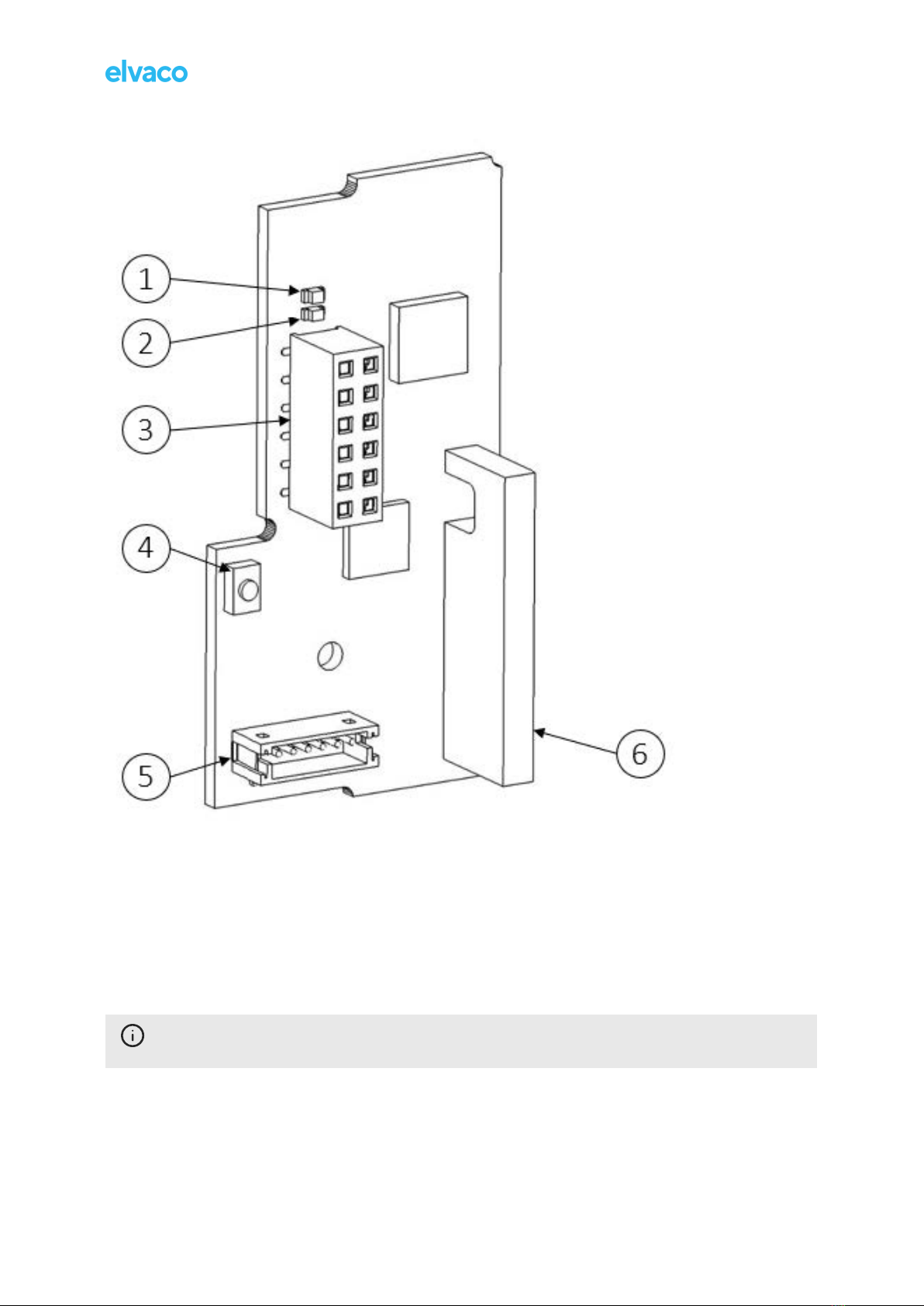
1. Green LED
2. Red LED
3. Interface connector
4. Push button
5. Pulse input
6. LoRaWAN antenna
NOTE
The NFC antenna is integrated in the edge of the PCB.
CMi4170
7

4. Installation
4.1. Mounting the module
CMi4170 is mounted in an Engelmann Sensostar S3/S3C meter.
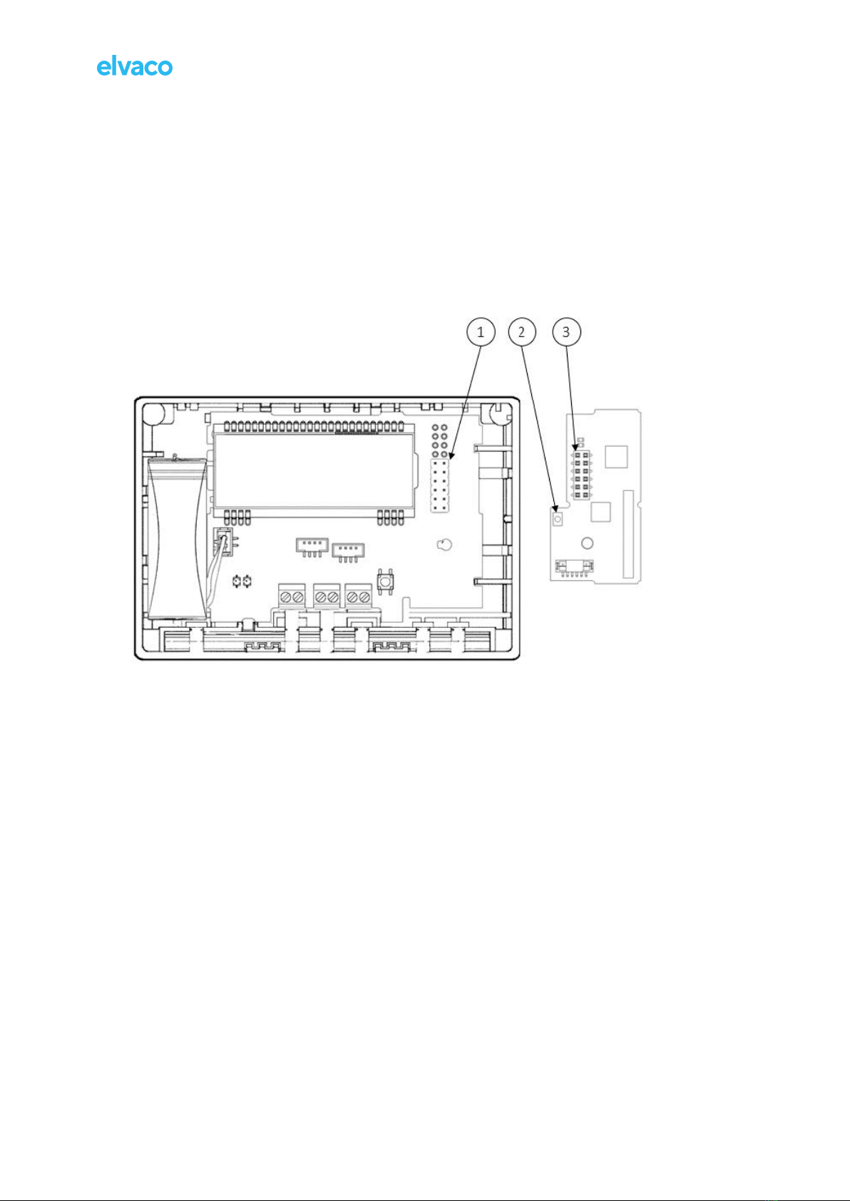
1. Grab the device by the outer edges.
2. Gently press it into postition in the module slot.
• Make sure that the module's push button (2) is facing upwards.
• Make sure that interface connector of the meter (1) fits the interface connector of the module (3).
Engelmann Sensostar (left), CMi4170 (right)
4.2. Activating the module
Upon delivery, CMi4170 is set to passive mode, which means no messages will be transmitted from the
module. The module can be activated in one of the following ways:
Via the module push button
1. Press down the push button of the module for at least five seconds.
2. Release when the green LED lights up.
3. Wait for one to eleven seconds.
The module indicates start-up by flashing red and green LEDs for one second.
Via Elvaco OTC app
1. Open Elvaco OTC app (downloadable via Google Play).
2. Scan the module (make sure NFC is activated on the phone).
3. Go to Apply mode.
4. Set the power mode to “Active”.
5. Select Apply settings.
6. Scan the module to apply new settings.
To verify that the module has been activated, go to the Inspect, scan the module, and make sure
that power mode is set to “Active”.
CMi4170
8

TIP
The NFC field is easiest accessible if placing the phone in the middle part of the front.
Via device monitor
Device monitor refers to Engelmann's optical configuration tool. For more information see Engelmann
documentation.
Via meter menu
Refer to Engelmann documentation.
4.3. Joining the LoRaWAN network
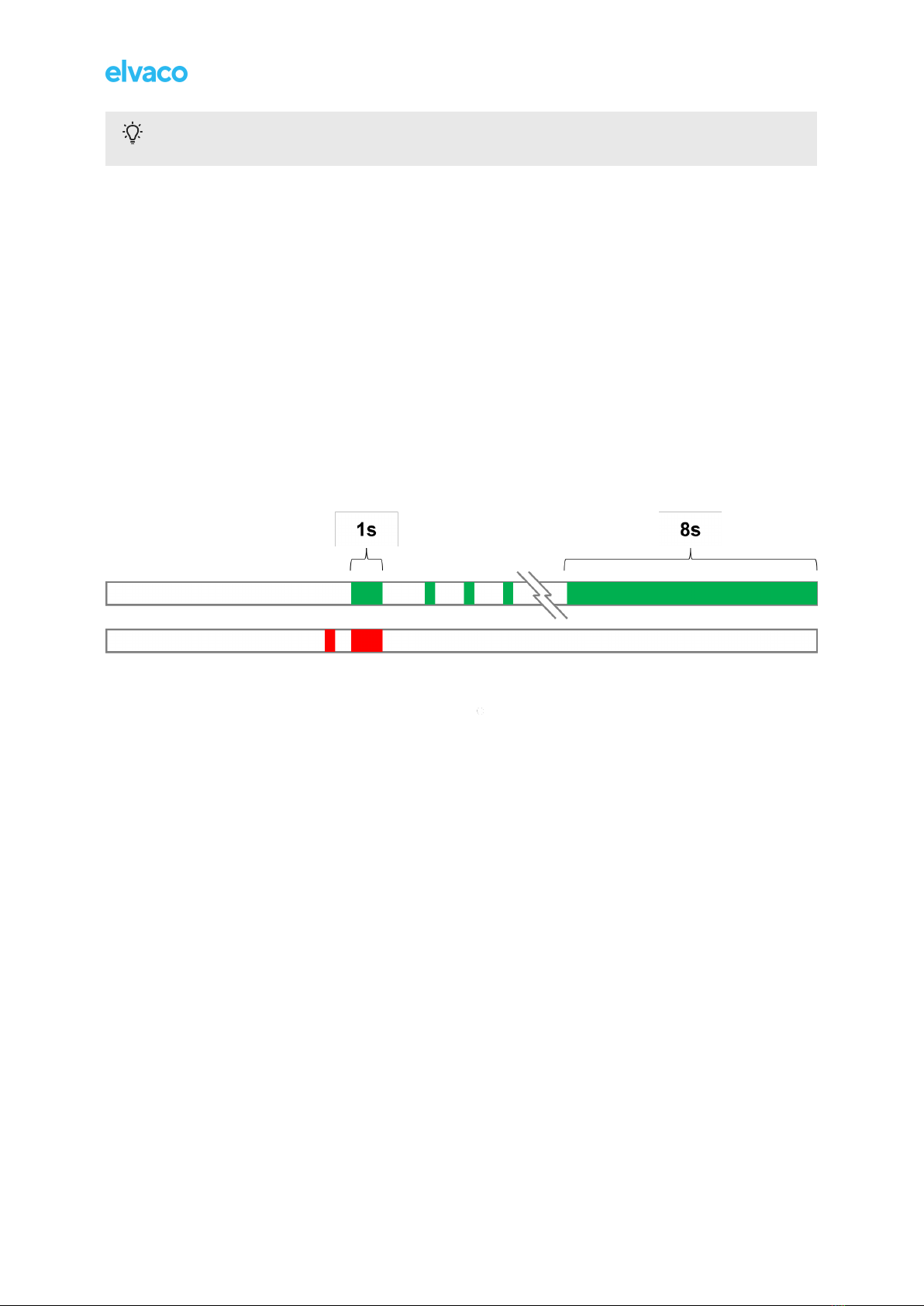
When activated, the product will attempt to join the LoRaWAN network by the following sequence:
1. Red LED – One flash
2. Green and Red LED – Lights simultaneously up for 1 second
3. Green LED – Several flashes while trying to connect to the LoRaWAN network
4. Green LED – Lights up for 8 seconds when module succeeds in joining the LoRaWAN network
The network join sequence is illustrated in the figure below:
Network join LED indication
If the module fails to join the LoRaWAN network, it will perform retries until it succeeds. The time
between each attempt will increase for every attempt until it is performed once every day. A new join
attempt cycle can be manually started anytime by using the push button to reboot the module or by
deactivating and activating the module using the Elvaco OTC App.
When the module has joined the LoRaWAN network, it will perform three quick transmissions (regard-
less of transmit interval settings) before starting to use its configured transmit interval settings. By using
the Elvaco OTC App, you can easily verify that the module is successfully communicating with the
meter (“Meter communication”) and is connected to the LoRaWAN network (“Network joined”).
CMi4170
9

5. Operation
5.1. Server configuration
There are two different activation types for LoRaWAN - Over-the-air activation (OTAA) and Activation by
personalization (ABP). Elvaco strongly recommends using OTAA, where all network keys are generated
each time the module joins the LoRaWAN network. In contrast, for ABP, all keys are set manually and
stay constant over time.
In OTAA mode
Before the module is able to transmit messages via the LoRaWAN network, device information needs
to be added to the network server. More specifically, the following parameters needs to be registered in
order to enable the network server to receive messages from the module:
Device EUI
The device EUI is a 16 digit module unique identification number. It is not configurable.
Application key
The application key of each device is generated by Elvaco and used in OTAA mode to generate
network keys when the module joins the LoRaWAN network. Keys are managed in a secure way
using Elvaco’s OTC (One Touch Commissioning) solution which includes the mobile application for
configuration.
Join EUI
The Join EUI sets the identification number of the application server where data from the module shall
be delivered. The identification number is set to a default value in all devices. The default value is
presented in Elvaco OTC configuration options.
In ABP mode
If the activation mode is set to ABP, the application key does not need to be added to the network
server. Instead the following information will be needed:
• Network session key
• Application session key
• Device address
5.2. Configuration
Via Elvaco OTC app
The module is configured via the Elvaco OTC app. The app uses NFC to transfer settings to the
module. It is compatible with iPhone or Android phones with Android 5.0 or later. The OTC app can be
downloaded from Google Play for Android and App Store for iOS.
It is possible to create a configuration profile to apply preconfigured settings to multiple devices. For
further information, refer to the OTC app documentation, available on the Elvaco website.
1. Open the Elvaco OTC app on your smartphone.
2. Place your smartphone close to the device and press SCAN.
3. After a successful scan, the current settings will be displayed on the INSPECT tab.
4. To change settings, go to the APPLY tab. Use the toggle button to activate an option, and make
your changes.
5. When done with changes press APPLY at the bottom of the screen, then Apply settings. Repeat
step 2 to change the settings in the device.
CMi4170
10
Andere Handbücher für CMi4170
2
Inhaltsverzeichnis
Andere Elvaco Messgerät Handbücher

Elvaco
Elvaco CMi6140 Bedienungsanleitung

Elvaco
Elvaco CMi6110 Bedienungsanleitung

Elvaco
Elvaco CMi6140 Bedienungsanleitung

Elvaco
Elvaco CMi4170 Bedienungsanleitung

Elvaco
Elvaco CMe3100 Bedienungsanleitung

Elvaco
Elvaco CMe2100 gen.3 Bedienungsanleitung

Elvaco
Elvaco CMi4110 Bedienungsanleitung

Elvaco
Elvaco CMe2100 Installationsanleitung

Elvaco
Elvaco CMeX10S Installationsanleitung

Elvaco
Elvaco CMi6110 Bedienungsanleitung