
enware DFSA121-PBBF Bedienungsanleitung

I00443_Dec 21
Installation and Maintenance Instructions
Freestanding Water Chiller with
Hands-Free Bottle Filler
DFSA121-PBBF
enware.com.au

2 Call 1300 369 273 www.enware.com.au
937
245
295
320
320
805 -810 MAX
160
75
160
½” WATER
INLET
40mm DRAIN
CONNECTION
BACK FACE OF WATER CHILLER
product description
Enware water chillers supply chilled water on demand. Supplied with heavy duty bottle
ller - to ll a bottle push the bottle against the button and hold. Drinking bubbler can be
removed, to optimise hygiene, with supplied deletion kit. Suitable for public areas such as
gyms, building sites and ofce buildings.
KEY FEATURES
• Flow rate of up to 18 litres/hour of chilled water
• 4 Litre storage tank
• Easy hands-free lling of bottles: Simply push the bottle against the button, no need
for the hand to touch any handle
• Hygienic, polished stainless steel tops designed for rapid draining
• Adjustable levelling feet
• Stainless steel storage tank
• FDA approved internal pipework
• Environmentally friendly R134A refrigerant
• Side carry handles and removable front access panel for easy installation
• Includes internal waste trap
• Supplied with bottle ller ready to t and including delete kit for bubbler if it is not required
BOTTLE FILLLER
BUBBLER
WATER CHILLER
All measurements are in millimetres.
937
245
295
320
320
805 -810 MAX
160
75
160
½” WATER
INLET
40mm DRAIN
CONNECTION
BACK FACE OF WATER CHILLER
937
245
295
320
320
805 -810 MAX
160
75
160
½” WATER
INLET
40mm DRAIN
CONNECTION
BACK FACE OF WATER CHILLER

www.enware.com.au Call 1300 369 27 3
IMPORTANT - This must be read before proceeding with installation
1. Enware products are to be installed in accordance with the Plumbing Code of Australia
(PCA) and AS/NZS3500. Installations not complying with PCA and AS/NZS 3500 may
void the product and performance warranty provisions. Reference should also be made
to the ABCB and Local Government regulations when considering the choice of, and the
installation of these products.
2. Electrical installation must be in accordance with AS/NZS3000-2018.
3. Water connection to the water cooler should be made through an approved Non-Return
Isolating Valve/ Stop Tap and installed in an accessible position.
* Note: Non-Return Isolating Valves/Stop Taps are not supplied with this product.
4. Water supply pressure must not exceed 500kPa. It is recommended that an approved
500kPa Pressure Reduction Valve be installed with all water chillers to safe-guard against
pressure surges that may occur in the supply lines, especially at night.
5. For use with potable water only.
NOTE: Enware Australia advises:
1. Due to ongoing Research and Development, specifications may change without notice.
2. Component specifications may change on some export models.
installation compliance
technical data
Chilled Water Production up to 18 Litres/hour
Recommended Water
Supply Pressure
50-500 kPa
(Use of pressure reduction valve is recommended if inlet pressure
may exceed 500 kPa)
Power Supply 240V / 50 Hz
Power Connection 3 pin 10 A plug with 2m lead
IP Rating IP23
Water Inlet Connection 1/2” BSP male
Water Drain Connection 40mm DWV PVC
Storage Tank 4 Litres
Compressor Size 362 W
Condensor Wire tube
Refrigerant R134A
Climate Condition SN.N *
Net Weight 30kg
Bottle Filler Flow Rate 2 L/min - 7 L/min
adjustable
* Suitable for use in ambient temperatures of 10°C to 32°C

4 Call 1300 369 273 www.enware.com.au
WARNING:
• Enware water chillers are not suitable for outdoor use. The appliance must not be exposed
to rain.
• Stainless steel panel (non-powder coated) chillers are not designed or recommended for
use in corrosive environments such as enclosed chlorinated pool areas.
• Consideration must also be made at the time of installation to adverse environmental/
atmospheric conditions such as, but not limited to, dust, corrosion, or freezing. These
conditions may void the warranty.
• Do not operate this appliance at ambient temperatures below 0°C, as it may cause the
water inside the water chiller to freeze and damage internal components.
• The appliance is not suitable for installation in an area where a water jet could be used.
• This appliance is not intended for use by persons (including children) with reduced
physical, sensory or mental capabilities, or lack of experience and knowledge, unless they
have been given supervision or instruction concerning use of the appliance by a person
responsible for their safety. Children should be supervised to ensure that they do not play
with the appliance.
CAUTION:
• Mains Power Electrical Components. For the purpose of safety and hygiene, access to
the internal components of this appliance is restricted to persons having knowledge and
practical experience of the appliance.
• Ensure the electrical supply is turned off, before taking the front panel off to access internal
components.
• If the power supply cord is damaged, it must be replaced by the manufacturer, its service
agent or a qualified electrician in order to avoid a hazard.
• In order to avoid a hazard due to inadvertent resetting of the thermal cutout, this appliance
must not be supplied through an external switching device, such as a timer, or connected
to a circuit that is regularly switched on and off by the utility.
• Do not damage the refrigerant circuit. Care should be taken not to puncture refrigeration
system lines. Some lines contain gas under high pressure.
• Keep ventilation openings, in the appliance enclosure or in the built-in structure, clear of
obstruction.
• Do not use mechanical devices or other means to accelerate the defrosting process, other
than those recommended by the manufacturer.
• If freezing occurs, do not operate the appliance, until ambient temperatures is again above
0°C and frozen unit has completely thawed.

www.enware.com.au Call 1300 369 27 5
FRONT
PANEL
FIXING
SCREWS
installation
DFSA121-PBBF water chiller is ready for final assembly on
site.
Remove water chiller and bottle filler from the packaging.
Remove the front panel of the chiller unit by unscrewing
the two fixing screws. Pull panel forward and slide down to
remove the front panel. SEE IMAGE 1
IMPORTANT - Ensure chiller unit is disconnected from
power supply before accessing the inside of the chiller
unit.
INSTALLING BOTTLE FILLER
1. Fit bottle filler to the basin top of the water chiller,
ensuring the location pin fits into the pre-drilled hole.
Fit spacer washer and backnut from underneath, and
tighten the backnut with a spanner to secure the bottle
filler assembly. SEE IMAGE 2
2. Screw the tube adaptor to the 1/2” bottle filler thread,
ensuring that the rubber seal is in place in the adaptor -
tighten firmly, but do not overtighten. SEE IMAGE 2
3. Push the 1/4” tube firmly into the adaptor socket until
it bottoms out - pull back gently to check that the tube
has locked. SEE IMAGE 3
IMAGE 1
IMAGE 2
Push tube in to connect. Pull back gently on the tube
to check it is locked.
To disconnect, ensure the system
is depressurized, push the collet
square against the tting.
With the collet held in this position
the tube can be removed.
IMAGE 3
6 Call 1300 369 273 www.enware.com.au
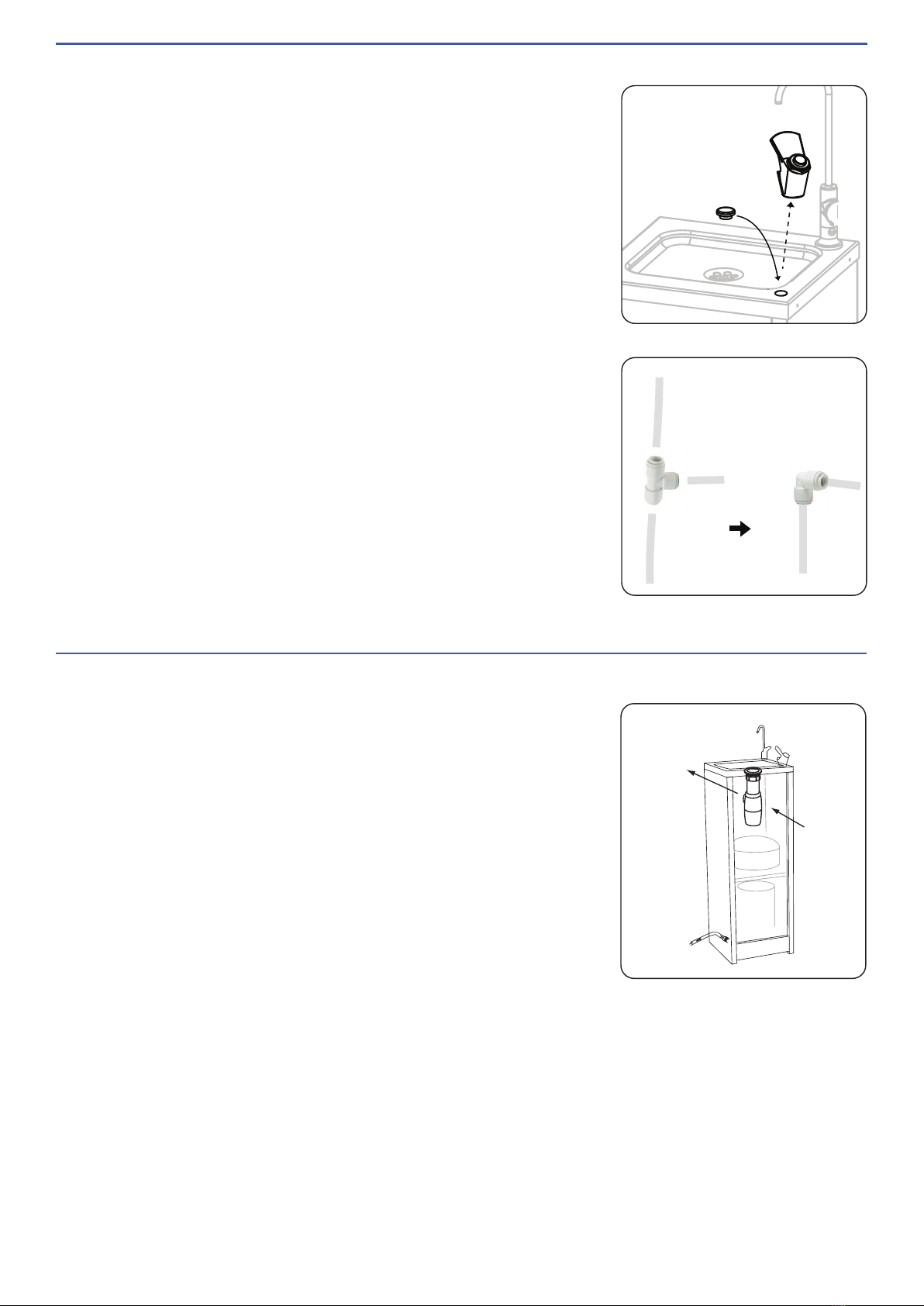
REMOVING BUBBLER (OPTIONAL)
The Water chiller is supplied with parts to allow the drinking
bubbler to be deleted or temporarily removed if not required.
1. Loosen and remove the back nut from under the bubbler.
2. Disconnect the 1/4'” tube by removing the small
compression fitting.
3. The bubbler can be removed and the rubber blanking
plug pushed into place. SEE IMAGE 4
4. Trace the 1/4” tube back to the tee-piece, then
disconnect all the tubes from the tee piece by holding the
collet at the joint in place and pulling the tube free from
the fitting. SEE IMAGE 3
5. Replace the tee-piece with elbow provided, connecting
the supply tube to the bottle filler. SEE IMAGE 5
IMAGE 4
IMAGE 5
CONNECT
TO 40MM
WASTE
BOTTLE
TRAP
WATER
INLET
IMAGE 6
WATER CHILLER INSTALLATION
1. Place water chiller in desired position and adjust levelling
feet so that the water chiller is stable and sitting level.
Note: This appliance must be placed in a horizontal
position. Ensure there is at least 50mm of gap between
the back of the unit and any wall for fan ventilation.
2. From inside of the chiller unit, connect the 40mm bottle
trap (supplied) to the waste connection located on the
underside of the top tray. Connect DN40 DWV PVC
drain pipe to the bottle trap. SEE IMAGE 6
3. (Optional) Install a carbon filter (DFS002F- sold
separately) inside the chiller unit.
Cut or disconnect the 1/4” tube that feeds the bottle filler
(&/or bubbler) and install the carbon filter in the line.
4. Install a non-return isolating valve or a stop tap (not
supplied) at the water supply as required. Flush all
foreign matter from the water supply line, then connect
water supply to the 1/2” BSP male inlet fitting located at
the rear of unit. SEE IMAGE 5

www.enware.com.au Call 1300 369 27 7
5. Turn the water supply on and purge the air from the
stainless steel chilling tank by pressing the push button
on the bubbler or turning on the bottle filler. Water may
spit from the outlets during this procedure and care
should be taken not to let water splash on walls and
furniture. Allow the water to flow for 5 minutes, starting
and stopping it frequently.
6. Check all plumbing for leaks. Check the bottle trap and
drain pipe connections for water-tightness.
7. Replace the front panel to the chiller unit.
8. Connect power cable to an electrical outlet.
(Electrical connection: a flexible 2m service lead, 3 pin
10 AMP plug supplied to connect the chiller to a 240V
50Hz AC supply.)
Turn power on. The refrigeration unit and the fans should
start to activate.
Once water is cooled and chiller function is checked,
turn off the power and disconnect the power cable.
Open the front panel and check all plumbing for leaks
once again.
IMPORTANT - Chiller unit must be disconnected
from power supply before accessing the inside of
the chiller unit.
9. Replace front panel of the water chiller and secure
the panel using screws provided.
Connect power cable and turn power back on.
Remove protective film from stainless steel panels.

8 Call 1300 369 273 www.enware.com.au
operation
PUSH
BUBBLER
To turn on water flow, push button down.
To turn off water flow, let go of button.
Water flow stops automatically.
Push to
Fill Bottle
BOTTLE FILLER
To fill a bottle, push the bottle against the
Push Button and hold.
Pull Away
to Stop
Water Flow
To turn off water flow, pull the bottle away
and let go of the Push Button.
Water flow stops automatically.

www.enware.com.au Call 1300 369 27 9
flow adjustment
BOTTLE FILLER
Adjusting water flow rate (2 L/min - 7 L/min):
1. Unscrew and remove the regulator screw
cover cap using a slotted screw driver.
(Note this is only a cover - the regulator
screw is inside once the cover is removed.)
2. Locate the regulator screw inside. Turn the
spring action handle on full and adjust the
screw - tighten to reduce the flow or loosen
to increase the flow.
3. Once the desired water flow is achieved, put
the cover cap back on.
-
+
Regulator
screw
inside
Cover cap
Regulator Screw
Location
HEX DRESS NUT
(892537)
PUSH BUTTON
CARTRIDGE
RETAINING NUT
CARTRIDGE
(BUB294)
SPOUT
BODY
T
YPE 61 SPANNER FOR CARTRIDGE RETAINING NUT (892530)
INLET SCREEN MESH (892531)
FLOW ADJUSTMEN
T
SCREW
BUBBLER
Adjusting water stream height:
1. Unscrew hex cover nut from bubbler
body using a spanner. The nut and
push button can be removed to reveal
the top of the spring cartridge and the
cartridge locking ring.
2. Locate the flow adjustment screw in
the top of the cartridge. While pressing
the cartridge to fully on position, using
a small slotted screwdriver, screw the
adjustment screw in to reduce stream
height, or out to increase stream height.
3. Replace the push button and hex cover
nut and tighten.
4. Re-test bubbler fountain for correct
operation.

10 Call 1300 369 273 www.enware.com.au
components & spare parts
BOTTLE FILLER
PART ENWARE
SALES CODE
Top assembly - bottle filler push
button BUB267
SBA BUB260L
Spring action SBA service kit
Includes 2x piston o-rings, 1x
spring, 1x light spring, 1x ball
bearing, 1x ball seating washer, 1x
seat o-ring, 1x red fibre washer
BUB289
Dome (with grub screw)
BUB221L
Grub screw 10-24 UNC x 3/16 SS 672455
Button spacer 693494
Colour indicator button - PUSH 672094
PART ENWARE
SALES CODE
Spout O-ring 672357
Regulator O-ring BS008 672345
Backnut (brass) MIS517
Backnut Spacer 672473
Allen key 3/32” MIS592
SBA
(BUB260L)
Button Spacer
Push Button
Dome
Grub Screw
Push Knob
Top Assembly
(BUB267)
Colour Indicator
Button
Backnut
Backnut Spacer
Cover Cap
Regulator
O-ring
Regulator Screw
Anti-Rotation
Pin
Spout
Spout O-ring
1/2” BSP x
1/4” tube
adaptor
Inhaltsverzeichnis
Andere enware Kühler Handbücher


