
FWC DWM-IV Bedienungsanleitung

Operator Manual
Model DWM-IV

Table of Contents
Standard Features:...........................................................................................................3
Options: ......................................................................................................................4
Specifications:.............................................................................................................4
Compliance with FCC Rules ...........................................................................................6
Warranty .........................................................................................................................6
Installation Re uirements................................................................................................7
Unpacking and Inspection...............................................................................................7
Handbook 44 Re uirements ............................................................................................7
Installation Instructions for Grounding Kit ......................................................................8
Operating Instructions.....................................................................................................9
A. DISPLAY...............................................................................................................9
B. STATUS INDICATORS ........................................................................................9
C. KEYBOARD..........................................................................................................9
D. FRONT PANEL FUNCTIONS ............................................................................ 11
Front Panel Data Entry .......................................................................................... 13
How to Enter and Exit System Setup............................................................................. 17
Configuration Setting Descriptions............................................................................ 18
Set-Up Procedure ...................................................................................................... 26
Calibration Procedure................................................................................................ 35
Error Codes During Calibration............................................................................. 38
Error Displays ........................................................................................................... 38
Programming Steps Summary....................................................................................... 39
Serial Bi-Directional Communications.......................................................................... 42
Remote Control Inputs .................................................................................................. 43
Data Output Formats..................................................................................................... 43
Custom Print Format Programming............................................................................... 48
Print Codes and Descriptions ........................................................................................ 49
Standard Current Loop Interface ................................................................................... 52
Connecting a Computer or Terminal to Your DWM-IV................................................. 52
Data Interface Connector Chart ..................................................................................... 53
Glossary........................................................................................................................55
U.S. ASCII Character Set.............................................................................................. 57

Standard Features:
Keyboard programmable setup: All select functions, setup and calibration are
programmable through the keyboard. Access to setup mode is enabled by internal switch.
Pushbutton Zero: Used for establishing gross zero.
Pushbutton Tare: Automatically tares the weight of object placed on the scale and
places scale in the net mode.
uto Zero Tracking: Automatically tracks zero (0) within 1/4 digit to ensure a stable
zero (0) over time.
Gross/Net Pushbutton: View net and gross weight when tare weight has been entered.
Print Pushbutton: Transmits data out of serial port.
Numeric ID: Single register to enter up to seven (7) digits of numeric identification.
CN: Six (6) digit consecutive number increments each time the [PRINT] button is
pressed.
Recall Tare Pushbutton: Used for recall viewing of tare weights.
Keyboard Tare Pushbutton: 10 Tare look-up (09) to enter predetermined tare values.
PC WT Entry: 9 piece weight look-up (19) determines count by entering pre-
determined piece weight.
Weight ccumulation: 10 weight accumulation registers with subtotal.
Digital Filter: Compensates for vibration or motion, keyboard selected from 1 to 32
updates per average.

Data Output: Serial ASCII 20 mA current loop with selectable baud rates (15019.2K),
selectable auto or manual print, continuous data out, or bi-directional communication.
Remote Control Inputs: Zero, Tare, Net/Gross, Print. Re uires voltage-free contacts.
Enclosure: NEMA-12 wall mount/dust-tight.
Options:
Outputs: Dual port serial RS-232, RS-422, RS-485, and/or 20mA current loop; Parallel
BCD; Analog 4-20mA or 0-5 VDC.
Time and Date: Battery backed up time and date with selectable 12 or 24 hour mode.
Setpoints: Up to six (6) single speed or three (3) two speed setpoints with Zero
Interlock and Fill Complete output.
Table Stand: Provides 60 degree angle mount stand for wall mount enclosure.
N4S Enclosure: NEMA-4 Stainless Steel watertight wall mount enclosure.
Custom Systems: Flex-Weigh offers full engineering support for customized systems.
Contact your local dealer for further details.
Specifications:
Keyboard: Sealed keyboard with tactile keys.
Display: 6 digits and (-) sign. Seven (7) segment, 0.5" high blue vacuum fluorescent
type, with annunciators for: function select, center zero, tare, net, pieces, F1, and F2.
Internal Raw Count: 100,000 counts maximum.
Display Resolution: 1 part in 10,000 maximum Legal for Trade, 1 part in 24,000
extended, 1 part in 100,000 maximum in high resolution mode.
Display Increments: x1, x2, x5, x10, x20, x50, x100.
Decimal Point Location: Selectable 14 places to the left.
/D Conversion Rate: 15 updates per second.
Response Time: Zero (0) to full scale capacity, selectable to 0.5 to 4 seconds.
Display Rate: Selectable 0.25, 0.5, 1, 2, 5, 10, or 20 updates per second.

Over Capacity: Displays OLOADat 102% of Full Scale Capacity.
Center Zero: Light indication when scale is within +/-0.25 digit of center of zero (0).
Load Cell Excitation: 15 VDC, powers up to twelve (12) 350 ohm load cells.
Input Sensitivity: 0.6 to 12 microvolts per digit.
ccuracy: 0.01% of full scale or +/- one digit, whichever is greater.
Data Output: Serial ASCII 20 mA current loop with selectable baud rates (15019.2K),
selectable auto or manual print, continuous data out, or bi-directional communication.
Operating Temperature: -10 degrees C to +40 degrees C (+14°F to +104°F).
Humidity: Maximum: 95% RH non-condensing.
Power: 120 or 240 VAC, 5060 Hz, 25 watts.
Fuse: 1/4A @ 120 VAC, 1/8A @ 240 VAC.
Dimensions: 12" (30.48 cm) H x 10" (25.4 cm) W x 5" (12.7 cm) D.
Weight: 16 lb (7.25 kg).

Compliance with FCC Rules
Please note that this e uipment generates, uses and can radiate radio fre uency energy. If
this e uipment is not installed and used in accordance with the instruction manual you are
warned that it may cause interference to radio communications. This unit has been type
tested and found to comply with the limits for a Class B computing device in accordance
with the specifications in Subpart J of Part 15 of FCC Rules, which are designed to
provide reasonable protection against such interference in a commercial environment.
However, if this unit is operated in a residential area, it is likely to cause interference and
under these circumstances the user will be re uired to take whatever measures are
necessary to eliminate the interference, at his/her own cost.
Warranty
Flex-Weigh Corporation (hereinafter called FWC) warrants that articles, materials and
work furnished by them will conform to specifications, drawings and to other data cited,
further stipulating that such material and workmanship shall be free from defect. FWC
will repair or replace at its discretion, free of charge, any e uipment covered by this
warranty which is returned within one year of installation or fifteen months after initial
delivery and which upon examination proves to be defective in nature or workmanship.
This warranty does not apply to any FWC product that has been:
1) Repaired or modified by anyone other than someone authorized by FWC if in their
judgment such repair or modification has detrimentally affected the performance or
reliability of the product.
2) Improperly installed or not adjusted in accordance with instructions provided by FWC.
3) Mishandled, abused, or in the judgment of FWC has been exposed to an environment
for which the product was not designed.
This warranty constitutes FWCs exclusive warranty, there being no other warranties
expressed or implied, including any warranty of merchantability or fitness for a particular
purpose.

Installation Requirements
Maximum performance is guaranteed only when installation of the scale system is
performed by a ualified scale technician. For best performance, the AC mains supplying
the scale system must be an isolated circuit free from other loads and not in close
proximity to inductive or SCR controls.
WARNING: THIS SCALE MUST BE OPERATED FROM AN AC POWER SOURCE
THAT PROVIDES AN EARTH GROUND FOR THE SCALE CHASSIS TO ENSURE
SAFE OPERATION AND PROPER PERFORMANCE. THE POWER CORD IS THE
POWER DISCONNECT DEVICE. CARE SHOULD BE TAKEN NOT TO BLOCK
ACCESS TO THE OUTLET IN CASE OF AN EMERGENCY.
Unpacking and Inspection
Remove the weightmeter display from its shipping container. Discard the protective
materials. Do not plug the meter into an AC voltage source until completing the
inspection of the instrument. With a proper screw driver, loosen the screws holding the
lid clasps in place. Open the lid and visually inspect to make sure there are not signs of
shipping damage such as broken wires, loose components, or fractured printed circuit
boards. This visual inspection is necessary if a shipping claim needs to be processed.
Every care has been taken to minimize potential damage that could occur if rough
handling is experienced in transit.
Handbook Requirements
The following applies to Model DWM-IV weightmeters used on Handbook 44
applications.
1) Wire seal provision is re uired on access lid.
2) Piece count feature must be disabled (Step F5.0 of SET-UP procedure).
3) RFI (Radio Fre uency Interference) protection kit option is re uired in areas where
RFI is present.
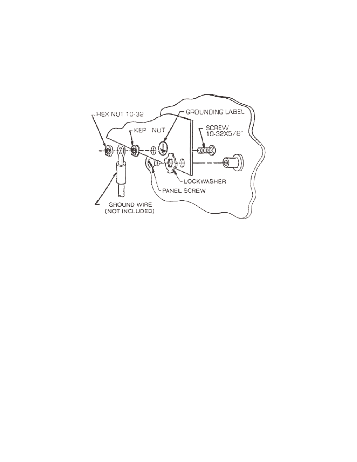
Installation Instructions for Grounding Kit
Part No. 99411-399
1. Insert the 5/8 long screw through the hole in the panel as shown.
2. Secure screw with kep nut. The kep nut must bite into the paint to insure electrical
continuity.
3. Attach the ground wire and secure with 1032 hex nut as shown.
4. Install the lockwasher under one of the screws securing the panel to insure grounding
between the panel and the enclosure.
5. Attach grounding label included adjacent to the bolt as shown.
Rev. D
Hoffman Engineering Company
900 Ehlen Drive
Anoka, Minnesota, 55303-7054, U.S.A.
Phone (612) 421-2240 Fax (612) 421-1556

Operating Instructions
A. DISPLAY
The display indicates the arithmetic result of the analog signal derived from the scale
base. The display indicates: OLOAD at 102% of capacity and above.
B. STATUS INDICATORS
The DWM-IV illuminates a triangular arrow above the proper legend for current status of
the display. The status indicators are:
1. SEL - illuminated while accessing the front panel options.
2. ZERO - illuminated when the scale base is within +/- 0.25 increment of zero
3. TARE - when lit, indicates that a tare value is being displayed.
4. NET - when lit, indicates that a non-zero tare value is currently being used.
5. PIECES - illuminated when in the piece count mode to indicate that the display is
showing pieces instead of weight.
6. F1 - Future option. (not labeled on standard units)
7. F2 - Future option. (not labeled on standard units)
C. KEYBOARD
1. [Zero] Button: This button allows re-zeroing of the scale over a +/- 2% range of scale
capacity or full scale capacity (programmable). During set-up, the automatic zero tacking
may be disabled if desired. This button must be pressed for approximately two seconds to
capture zero.
2. [Tare] Button: This button is used to remove the container weight value from the
weight indication. When pressed with weight on the scale no motion present, this tare
value will be stored and subtracted from the gross weight to indicate a net weight display
of zero. Pressing the [TARE] button places the system in net weighing mode.

3. [Gross/Net] Button: If a tare has been entered, this button will alternately select
between the gross and net weight modes. If the tare has been cleared to zero, the DWM-
IV will automatically select the gross weight mode. This button will be inactive while the
tare value remains e ual to zero.
4. [Print] Button: This button initiates a print cycle to an external peripheral device such
as a ticket printer or computer. The output format may be programmed during the set-up
procedure.
5. [Recall] Tare: The instrument is e uipped with a key board to provide a means of
entering a known tare weight. Up to six (6) digits of digital tare may be entered up to the
full capacity. Entries greater than full capacity will be cleared to zero. The least
significant digit (LSD) is automatically rounded to conform to the pre-programmed
instrument LSD. Press the [RECALL TARE] button then a numeric button corresponding
to the tare register desired (if ten (10) tare look-up feature is enabled) and the [ENTER]
button. The previously displayed data will be shown. Enter the re uired value and press
[ENTER]. This value is then stored in memory. A non-zero value places the system in net
weighing mode.
6. [Select]: This button is used to access the pre-programmed front panel functions as
indicated on the corresponding buttons zero through nine.
7. [Clear]: Used to clear a mistaken entry while in one of the data entry modes.
8. [Enter]: This button is used to store data into memory and also to se uence through the
data entry procedure.


