Geometrics MetalMapper 2x2 Bedienungsanleitung

MetalMapper 2x2
Operations Manual
Revision 2.1
P/N 0071740-01
GEOMETRICS, INC.
2190 Fortune Drive
San Jose, CA 95131 USA
Phone: (408) 954-0522
Fax: (408) 954-0902

1
Table of Contents
BATTERY SAFETY ............................................................................................................................. 3
1. Introduction .............................................................................................................................. 4
2. System Overview......................................................................................................................... 5
2.1 Data Acquisition Electronics and Software ....................................................................... 6
3. System Setup............................................................................................................................... 7
3.1 Cart Assembly .................................................................................................................... 7
3.2 GPS/IMU Tower ................................................................................................................. 9
3.3 Data Acquisition Electronics Backpack ............................................................................ 11
3.4 Cable connections............................................................................................................ 12
3.5 Batteries........................................................................................................................... 14
3.6 Skid steer mode ............................................................................................................... 15
4. Quick Start Guide ...................................................................................................................... 17
4.1 System connection .......................................................................................................... 17
4.2 System Configuration ...................................................................................................... 19
4.3 Parameter Setup.............................................................................................................. 20
4.4 QC Settings....................................................................................................................... 22
4.5 Survey Window................................................................................................................ 22
4.6 Measurement Types........................................................................................................ 25
4.7 Sample Project File .......................................................................................................... 25
5. Sensor QC Features................................................................................................................... 27
5.1 Static Function Test (SFT) ................................................................................................ 27
5.2 Dynamic Function Test .................................................................................................... 30
5.3 Reference SBG ................................................................................................................. 30
6. Static and Dynamic Measurements .......................................................................................... 32
6.1 Static Measurements....................................................................................................... 32
6.2 In-Field Inversion ............................................................................................................. 33

2
6.2 Dynamic Measurements.................................................................................................. 36
7. Instrument Settings................................................................................................................... 37
7.1 Application.properties file............................................................................................... 37
7.2 IMU Overview.................................................................................................................. 39
7.2 Calibrating the IMU ......................................................................................................... 39
7.3 GPS Configuration............................................................................................................ 39
7.4 Using a Robotic Total Station (RTS) or other external device ......................................... 40
8. Data File Format........................................................................................................................ 41
8.1 HDF5 files and export ...................................................................................................... 41
9. System Diagnostics and Troubleshooting................................................................................. 52
10. Storage and Maintenance....................................................................................................... 54
10.1 Lithium Ion Battery Shipping Guidelines for Customers ............................................... 54
10.2 Packing the Shipping Crate ............................................................................................ 55
Appendix I: Standard Inventory List.............................................................................................. 60
Appendix II: Theory of Operation ................................................................................................. 61
Appendix III: Application.properties file ....................................................................................... 63
Appendix IV: Importance of Valid Background Measurements ................................................... 65

3
BATTERY SAFETY
WARNING- Do not damage the rechargeable Lithium Iron Phosphate batteries. A damaged
battery can cause an explosion or fire, and can result in injury or property damage.
Do not use or charge the batteries if they appear to be damaged. Signs of damage may
include punctures, leaks, or warping.
Do not expose batteries to fire or prolonged high temperatures.
Do not immerse the batteries in water.
Do not drop or puncture the batteries.
Do not open the batteries or short-circuit the contacts.
Discontinue using or charging the batteries if they give off strong odor or extreme heat.
Charge the batteries only with approved chargers.
See Chapter 10 of this manual for Shipping Information.

4
1. Introduction
This manual is a User’s Guide for the Geometrics MetalMapper 2x2 geophysical instrument
used for the detection and characterization of Unexploded Ordnance (UXO). This instrument is
based on the Naval Research Laboratory TEMTADS MP 2x2 Cart system developed over the past
several years.
The system uses time domain electromagnetic (TDEM) principles to induce electrical currents in
buried metallic objects and then measures the effects of those currents in receivers on the
surface. It has four (4) co-planar transmitter coils placed in a 2 by 2 square. Each transmitter
coil is approximately 35 cm x 35 cm in size. Located in the center of each transmitter coil is a 10
cm x 10 cm x 10 cm receiver cube, each one containing three (3) orthogonal coils to measure
the fields resulting in 12 different receiver coils. The receiver coils are oriented in 3-dimensions.
The transmitter coils are powered using a bi-polar half duty cycle and the time decay of the
subsurface currents (transients) are measured during time off of the transmitter coils.
The MetalMapper 2x2 can be used in two collection modes, dynamic or static. Dynamic mode
is collected by pushing the cart over targets in a series of closely spaced parallel lines.
Navigation features in the software direct the user to stay on the correct path. Static mode is
collected by moving the instrument over predefined targets from an anomaly list. This
anomaly list can be derived from the results of a dynamic survey, or from another previous
geophysical survey (EM61-MK2 for example).
Data is collected and stored in a HDF5 file format. This format is self-describing and easy to
read and edit with many available free software packages. This manual does not cover any
post-processing of the HDF5 files to invert the data and identify the buried metallic objects.

5
2. System Overview
The MetalMapper 2x2 is comprised of four transmitter coils approximately 35 cm x 35 cm in
size. Located in the center of each transmitter coil is a 10 cm x 10 cm x 10 cm receiver cube,
each one containing three (3) orthogonal coils to measure the fields resulting in 12 different
receiver coils. The receiver coils are oriented in 3-dimensions. The center-to-center distance of
each receiver cube is approximately 40 cm. The sensors are mounted on a platform that is
typically 26 cm above the ground surface. A GPS and IMU (inertial measurement unit) are
mounted on a tower centered above the sensor platform. The transmitter electronics and
batteries are mounted on a backpack carried by the operator. The system is operated from a
tablet computer running the MetalMapper software.
Figure 2.1: Cart layout showing naming convention of A, B, C, D transmitter coils and receiver
cubes. X, Y, and Z coordinates are positive in the directions shown.

6
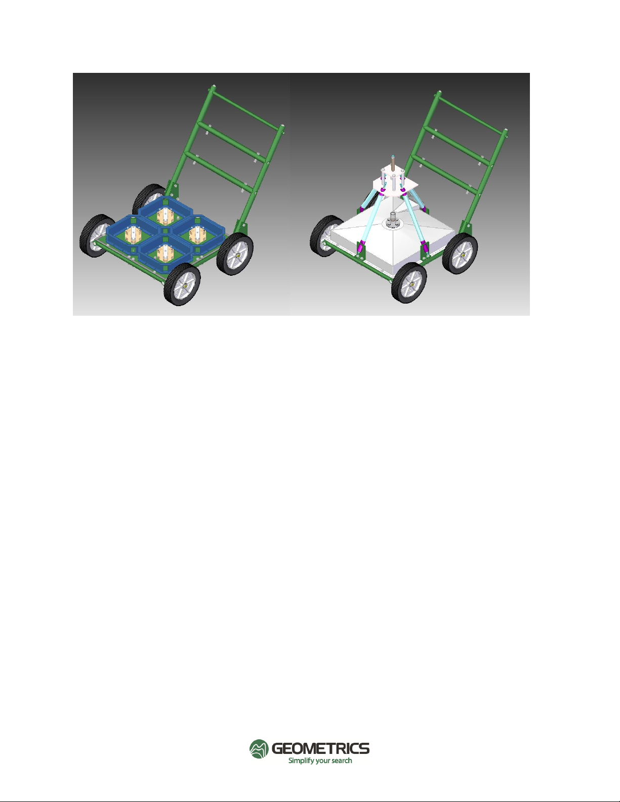
Figure 2.2: Sensor platform with top cover removed. Sensor platform fully assembled.
2.1 Data Acquisition Electronics and Software
The data acquisition electronics and batteries are mounted on a backpack worn by one of the
operators. The electronics are connected to the cart by 3 cables: Tx Cable, Rx Cable, and
GPS/IMU Cable. The second operator controls the system from a tablet computer running the
MetalMapper software and connected to the electronics via an Ethernet cable. Navigation is
directed by the software.

7
3. System Setup
The MetalMapper 2x2 system is packed and shipped in a collapsible plastic crate (P/N MM2x2
Crate) secured with banding. The crate dimensions are 48 in x 44 in x 36 in with a packed
weight of approx. 350 lbs. (shipping weights and dimensions may vary). Foam inserts are cut to
protect and secure the instrument during shipment. See Chapter 10 for more information on
packing and unpacking the system from the shipping crate.
3.1 Cart Assembly
The 4 transmitter coils (Tx) and 4 receiver cubes (Rx) are attached to the sensor platform with
plastic bolts. These items should not be removed or replaced unless instructed to do so by the
project geophysicist. The Rx cubes and Tx coils are covered by a piece of plastic attached to the
sensor platform. The cover should remain attached under most conditions. There is a cable
connection facing the rear of the sensor platform. The sensor platform cover should not be
removed without consulting Geometrics for instructions on how to remove it without damaging
the cable connection.
The axles are attached to the sensor platform with the axle mounting brackets. Slide the axles
through the brackets. Attach the wheels and spacers to the axles as shown below. There are 3
plastic spacers and 1 washer placed on the axle between the wheel and the hub. The wheel can
be secured to the axle on the outside with the small nut and bolt included, or with an optional
zip-tie.

8
Figure 3.1: Axles with wheels and spacers installed. Note optional zip ties to secure wheels.
Take care to avoid getting debris inside the wheel hubs and axles. Wheels and axles should be
periodically checked for debris and cleaned to prolong the life. The wheels do not need
lubrication during normal operation.
The cart handle will ship preassembled and only needs to be attached to the cart. The
mounting brackets have different mounting holes depending on the desired height of the
handle
.
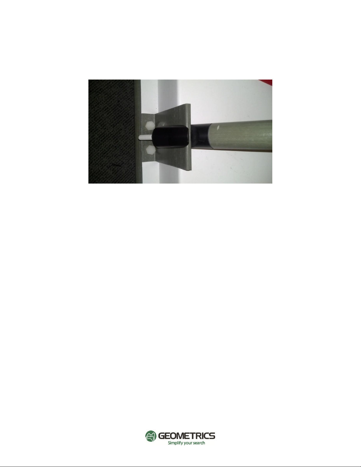
Figure 3.2: Handle attachment

9
3.2 GPS/IMU Tower
The GPS and IMU are installed on a 4-legged tower which is centered above the middle of the
sensor platform. Assemble each leg of the tower as shown below:
Figure 3.3: GPS tower legs
The GPS sits on the mounting bolt which is standard 5/8”-11 threaded nylon rod. The numbers
on the GPS tower legs must be installed so the number is right-side up. The legs are
interchangeable so the number positions do not matter. The height of the GPS above the
sensors is set using the GPS thread sheath attachment as shown below. It is helpful to use 2
nuts on the underside of the GPS tower rod and sheath to prevent the tower from loosening
during operation. The default height is set in the applications.property file. If this height is
changed from factory default see Chapter 7 on how to adjust the applications.properties file.
Andere Handbücher für MetalMapper 2x2
1
Inhaltsverzeichnis
Andere Geometrics Messgerät Handbücher

Geometrics
Geometrics G-864 Bedienungsanleitung

Geometrics
Geometrics MagArrow Bedienungsanleitung

Geometrics
Geometrics MagEx Bedienungsanleitung

Geometrics
Geometrics G-858BP Bedienungsanleitung

Geometrics
Geometrics Memory-Mag G-856AX Bedienungsanleitung

Geometrics
Geometrics Memory-Mag G-857 Bedienungsanleitung

Geometrics
Geometrics Memory-Mag G-857 Bedienungsanleitung

Geometrics
Geometrics MagArrow Bedienungsanleitung

Geometrics
Geometrics GemPen Bedienungsanleitung

Geometrics
Geometrics G-824A Bedienungsanleitung