
GREER Company MicroGuard 586 Bedienungsanleitung
MicroGuard ® 586 RCI Operation Manual 1 W458208C 05/11
MicroGuard® 586
Rated Capacity Indicator
System
For Industrial Cranes
Operation
Manual
Consider Yourself Warned™

MicroGuard ® 586 RCI Operation Manual 2 W458208C 07/2020
Table of Contents
Introduction ......................................................................................................................... 3
System Description ............................................................................................................. 4
Operator’s Display Console ................................................................................................ 6
Warning Alarm Indicators ............................................................................................... 6
Display Windows ............................................................................................................ 6
Push Buttons ................................................................................................................. 7
System Operation ................................................................................................................ 8
System Self Test ........................................................................................................... 8
Conguration Selection ....................................................................................................... 9
Normal Operation ........................................................................................................ 10
Approaching Overload ................................................................................................. 11
Maximum Capacity and Overload .............................................................................. 12
Two Block Warning ...................................................................................................... 12
Alarm Override ........................................................................................................... 13
Adjusting the Contrast ................................................................................................ 13
System Care ................................................................................................................. 14
Routine Checks and Maintenance .............................................................................. 14
Routine Checks and Maintenance .................................................................................... 15
Reel-Off Cable ............................................................................................................. 15
Routine Checks and Maintenance .................................................................................... 16
Hydraulic Connections................................................................................................. 16
Routine Checks and Maintenance .................................................................................... 17
Checking the Two-Block Warning Signals and Cutout of Machine Motions ................ 17
Routine Checks and Maintenance..................................................................................... 18
Load Test ..................................................................................................................... 18
System Fault Messages .................................................................................................... 19
Extension Reel Voltage Checks ........................................................................................ 21
Computer Internal Status Indicators .................................................................................. 22
Computer Replacement .................................................................................................... 24

W458208C 05/11 MicroGuard ® 586 RCI Operation Manual 3
Introduction
The MicroGuard® 586 System is designed for use as an aid to crane operation.
Note: Do not use this system in place of a properly trained operator who is knowledgeable in safety
guidelines, crane capacity information, and the crane manufacturer’s specications.
This manual describes the setup, operation, and troubleshooting of the MICROGUARD® 586
Rated Capacity Indicator/Limiter System (hereinafter referred to as “the system”). Please make sure to
read, understand, and follow the contents and instructions contained within this manual.
WARNING!
IMPROPER INSTALLATION OF THIS SYSTEM MAY RESULT IN SYSTEM MALFUNCTION!
W458208C 07/2020

MicroGuard ® 586 RCI Operation Manual 4
System Description
The system, which includes a computer, an operator’s display console, an extension reel, and various
cables and sensors; and is designed to measure and display load weight, calculate and display maximum
capacity and percent of rated capacity, display code conguration numbers, and warn of an approaching
overload or two-block condition for each crane conguration.
W458208C 07/2020

W458208C 05/11 MicroGuard ® 586 RCI Operation Manual 5
The computer provides all of the functions necessary to read the system sensors, work out computations,
and control the disconnect functions. In order to reliably calculate crane parameters, such as load and rated
capacity, and interpret the crane capacity chart and code conguration numbers, information dening the
physical characteristics of the crane has been loaded during factory setup.
Two hydraulic pressure sensors, housed in the computer assembly, measure the pressure in each side of
the boom lift cylinder. Other system sensors, mounted elsewhere on the crane, are connected to the com-
puter via electrical cables.
The reeling drum assembly measures the extended length of the telescoping sections of the boom and
enables calculation of load radius, load weight, and percent of rated capacity.
The anti two-block switch is used to signal a two-block condition.
The reel-off cable provides a path, from the boom head to the computer via the extension reel cable. This
path is used to send a two-block signal to the computer.
The extension reel cable provides a path to the computer for the two-block signal, the angle sensor, and the
extension sensor.
The boom angle sensor is housed within the reeling drum assembly and measures the angle of the boom.
The operator’s display unit translates data received from the computer and displays the actual load and
percent of rated capacity in the display console windows. Visual and audible warnings and alarms activate
when capacity limits are approached or exceeded, or when a two-block condition is encountered.
W458208C 07/2020

MicroGuard ® 586 RCI Operation Manual 6
Operator’s Display Console
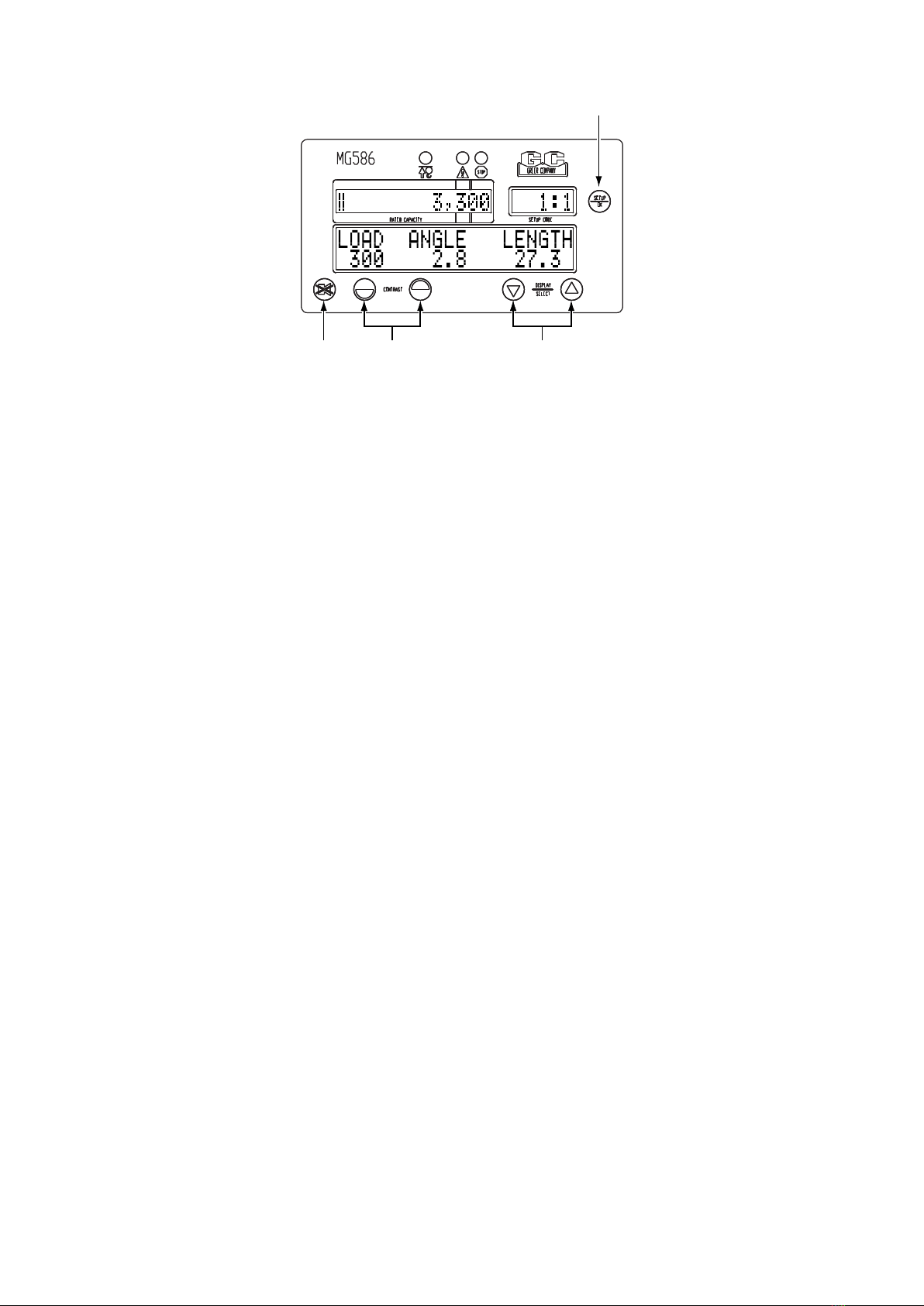
Warning/Alarm Indicators
The red two-block lamp will illuminate when a two-block condition occurs (see “Two-Block
Warning” on page 12).
The yellow pre-warning lamp will illuminate at 90% of rated capacity (see “Approaching Overload”
on page 11).
When the load reaches or exceeds 100% of rated capacity, the red overload warning lamp will
illuminate along with the yellow pre-warning lamp (see “Maximum Capacity and Overload” on page
12).
Display Windows
The current rated capacity for the crane in the current conguration will be displayed in the rated
capacity window as well as the percent of rated capacity shown as a meter which progresses to
the right as the load increases (see “Normal Operation” on page 10).
The setup codes are shown in the setup code window, as well as the parts-of-line, and the stowed
jib option if available (see “Conguration Selection” on page 9).
The information window shows crane specic information regarding boom length, boom angle, and
load radius, along with the load on hook. In addition, information regarding any warnings or alarms
will be displayed in this window. If the system has any internal faults, it will display “!WARNING!
SYSTEM FAULT” in the information window. The specic fault messages can be viewed by
pressing the UP ARROW or DOWN ARROW key (see “System Fault Messages” on page 19).
Two-Block Pre-Warning Overload and Fault
Rated Capacity
Information
W458208C 07/2020
W458208C 05/11 MicroGuard ® 586 RCI Operation Manual 7
Push Buttons
The SETUP key enables the operator to congure the system to match the actual setup of the crane.
Codes are present for:
• Stowed jib attachments; if no stowed options are available, this code will not appear.
• Crane conguration
• Number of parts-of-line
The ALARM OVERRIDE key is used to disable the audible warning and to override the function kick-out for
the current alarm condition.
The CONTRAST keys are used to adjust the lightness or darkness of the display area.
The DISPLAY MODE/SELECT keys are used to switch to different display formats showing various
combinations of boom angle, boom length, and radius. They can also be used as an UP ARROW or DOWN
ARROW key to scroll through menu selections.
Setup
Contrast Display Mode
Select
Alarm
Override
W458208C 07/2020

MicroGuard ® 586 RCI Operation Manual 8
System Operation
System Self-Test
When the system is turned on, it goes through a brief self-testing process.
All three alarm indicators will light up, all display windows will appear black, and the audible alarm will
sound.
The information display will then show the crane model and capacity chart number for the system
congured.
Following self-test, the system will go into the setup mode.
Refer to “Conguration Selection” on page 9 for setup instructions.
W458208C 07/2020

W458208C 05/11 MicroGuard ® 586 RCI Operation Manual 9
Conguration Selection
Conguration selection is required upon system power up; however, it can also be entered anytime by
pressing the SETUP key.
Note: If no stowed jib options are available, this selection option is skipped.
The stages for selection, in no specic order, may include the following:
1. O/R or rubber
2. Erected attachment
3. Stowed attachment
4. Parts of line
The current stowed jib code will be ashing and the jib description is displayed in the information window.
To select a different stowed jib, press the UP ARROW or DOWN ARROW key to display the desired option
and press the SETUP/OK key to continue.
The current number of parts-of-line is now ashing.
To change the parts-of-line, press the UP ARROW or DOWN ARROW key to select the desired number
and press the SETUP/OK key to continue.
Note: Some congurations allow only single part-of-line operation. In these cases, the whole parts-of-line
selection phase will be skipped and the parts-of-line will be set to one (1).
Once the correct parts-of-line are entered, the system will exit the conguration mode and return to the
normal working screen.
W458208C 07/2020

MicroGuard ® 586 RCI Operation Manual 10
Normal Operation
Rated Capacity
Percent of Rated
Capacity
Actual Load Boom Angle Boom Length
Percent of rated capacity indicates how near the operation is to full capacity and overload. The percent of
rated capacity meter progresses to the right as the percentage increases. As long as the meter remains
within the normal (green-bordered) zone, the percent of rated capacity is within normal operating limits.
When the percent of rated capacity exceeds 60%, the rated capacity text will move to the left (see
“Approaching Overload” on page 11).
Rated capacity is the heaviest load that the crane can lift in the current crane position and conguration.
This value may be limited by the number of parts-of-line selected, or an erected attachment.
The actual load appears in the information window under the word “LOAD”. The actual load includes the
weight of the load plus the weight of everything hanging below the boom tip (hook block, etc.).
The boom angle appears in the information window under the word “ANGLE”. This shows the current
angle of the boom in degrees and tenths of a degree. Depending on the operation, the “ANGLE” display
will change to “RADIUS”, in which case the radius from the centerline of rotation to the center of gravity of
the suspended load will be shown in feet and tenths of a foot.
The boom length is displayed in the information window under the word “LENGTH”. This shows the current
length of the boom in feet and tenths of a foot. By pressing the UP ARROW or DOWN ARROW button, the
display can be changed to show “ANGLE” or “RADIUS”.
W458208C 07/2020
Andere Handbücher für MicroGuard 586
3
Inhaltsverzeichnis
Andere GREER Company Messgerät Handbücher


