
Hummingbird HMSM2000CKIT Bedienungsanleitung

Version 1.3 – 30/11/2017 1
Installation and Operation Manual
HMSM2000CKIT Silent Horn Elite System for Trucks
HMSM2200CKIT Silent Horn Elite System for Diggers

Version 1.3 – 30/11/2017 2
CONTENTS
HMSM2000C Truck Installation .............................................................................................................. 3
1.1 HMSM2000C Truck kit ............................................................................................................ 3
1.2 Display Buttons ....................................................................................................................... 4
1.3 Truck Installation ..................................................................................................................... 4
1.4 Configuration Menu Options .................................................................................................. 8
HMSM2200C Digger Installation ........................................................................................................... 11
2.1 The HMSM2200C Digger Kit .................................................................................................. 11
2.2 Digger System Wiring Diagram ............................................................................................. 12
2.3 Interface Module Wiring ....................................................................................................... 12
2.4 Horn Button Switch: .............................................................................................................. 13
2.5 Setting the Digger Display ..................................................................................................... 14
HMSM2000C Truck Pairing Menu ......................................................................................................... 17
Fault Finding .......................................................................................................................................... 18
4.1 Antenna Indicator ................................................................................................................. 18
4.2 Display Error Messages ......................................................................................................... 19
Parts and Accessories ............................................................................................................................ 21
5.1 HMSM2000CKIT AND HMSM2200CKIT Main Components .................................................. 21
5.2 HMSM2000CKIT AND HMSM2200CKIT ACCESSORIES .......................................................... 22
5.3 HMSM1010CC WIRING LOOM .............................................................................................. 25
5.3.1 Wiring loom pinouts ..................................................................................................... 25
Version 1.3 – 30/11/2017 3
HMSM2000C TRUCK INSTALLATION
1.1 HMSM2000C TRUCK KIT
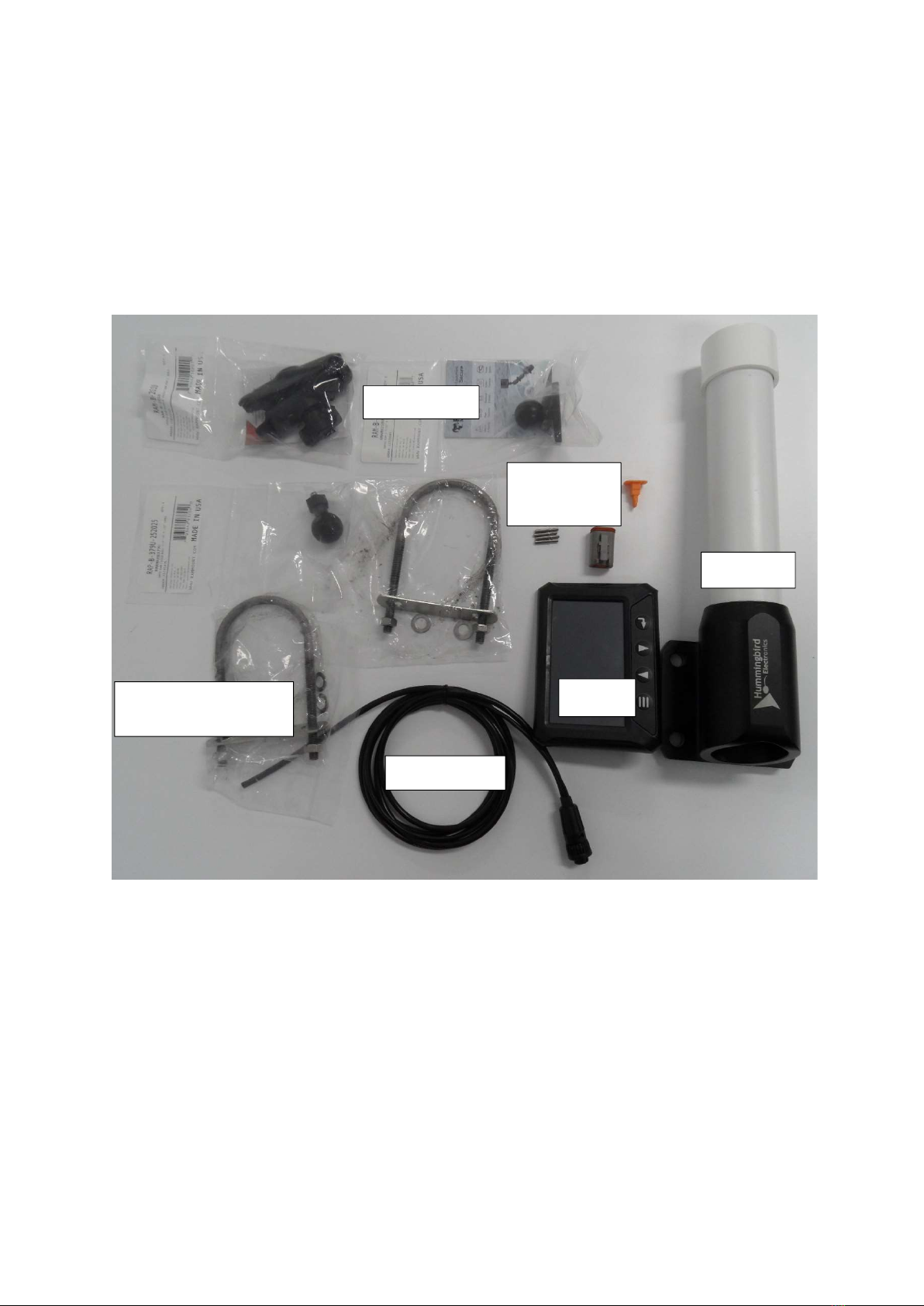
The following photo details the content of the truck kit
Display loom
2 x antenna mounting
brackets
RAM mount
Display
Antenna
Antenna
Deutsch plug
Version 1.3 – 30/11/2017 4
1.2 DISPLAY BUTTONS
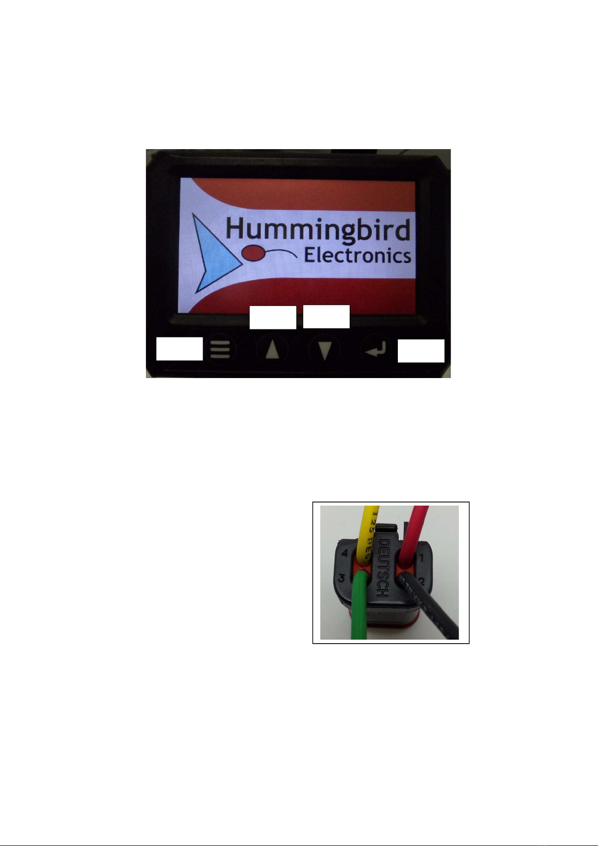
Throughout this manual there will be references to the display buttons. These buttons are identified
in the next photo.
1.3 TRUCK INSTALLATION
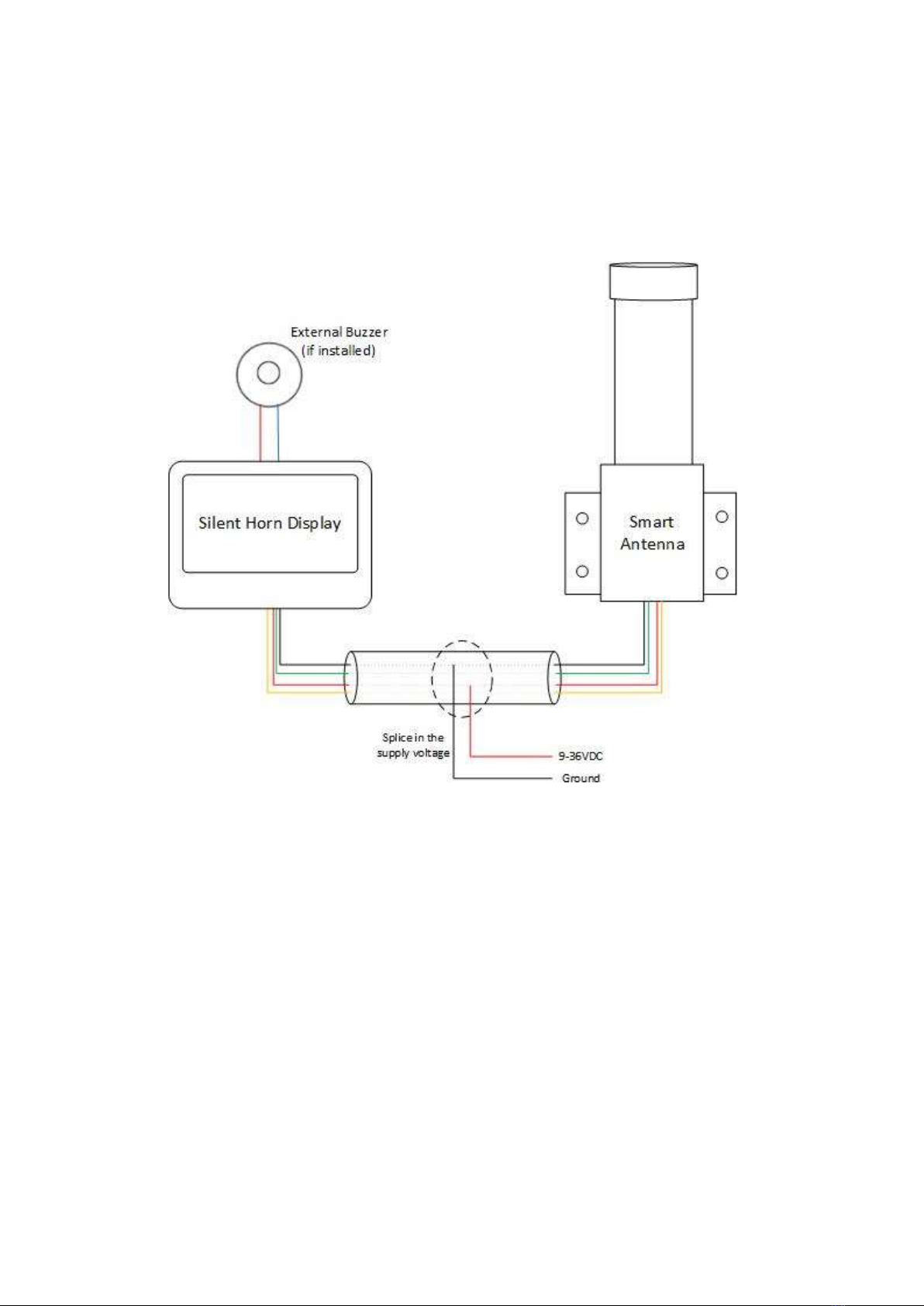
1.3.1 The display loom does not have the Deutsch connector for the antenna terminated, this is to
either allow for cable to be lengthened or shortened depending where the antenna is located. The
following figure details the pinout configuration for the antenna connector. Insert crimped wires into
Deutsch receptacle
Pin 1 Red
Pin 2 Black
Pin 3 Green
Pin 4 Yellow
Menu
Down
Up
Enter
Version 1.3 – 30/11/2017 5
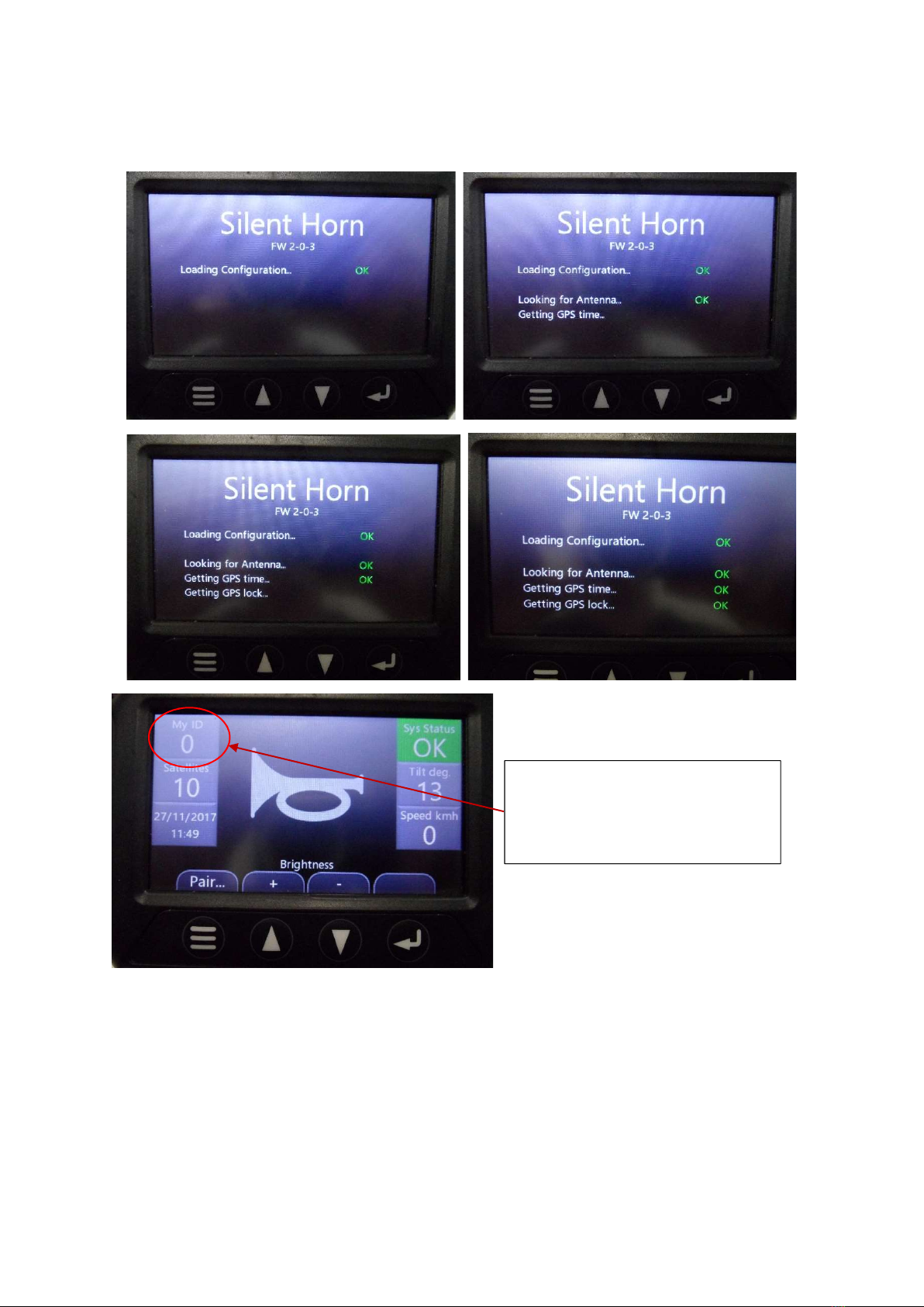
1.3.2 Splice the red and black wires from the supplied four core into the trucks power line, it is a
good idea to also place a 1A fuse in series whilst doing this. The other two pair cable on the
supplied loom (red and blue) is to allow for an external buzzer/alarm to be fitted, if you are
using one, do this now. See the wiring diagram below
1.3.3 Locate the antenna on a suitable structure of the truck and using the two mounting brackets
secure the antenna in place. When installing the antenna externally to the truck cabin, avoid
any obstructions over the antenna, this will significantly improve the amount satellites the
system will lock onto
Version 1.3 – 30/11/2017 6
1.3.4 Power up the unit by plugging in both the connectors. On start up the following messages
will be displayed
1.3.5 For the truck installation it is an optional choice whether to assign an ID. If this is a
requirement for your site, this is done by entering the configuration menu. The menu
system is accessed by holding down the menu button and the enter button at the same time
whilst the screen is powering up. The display has no on/off button, so to re-start the display
you press and hold the menu button for five seconds until the screen goes blank.
When the system is powered up for
the first time, the screen will display
the following default ‘My ID’ setting
of ‘0’
Version 1.3 – 30/11/2017 7
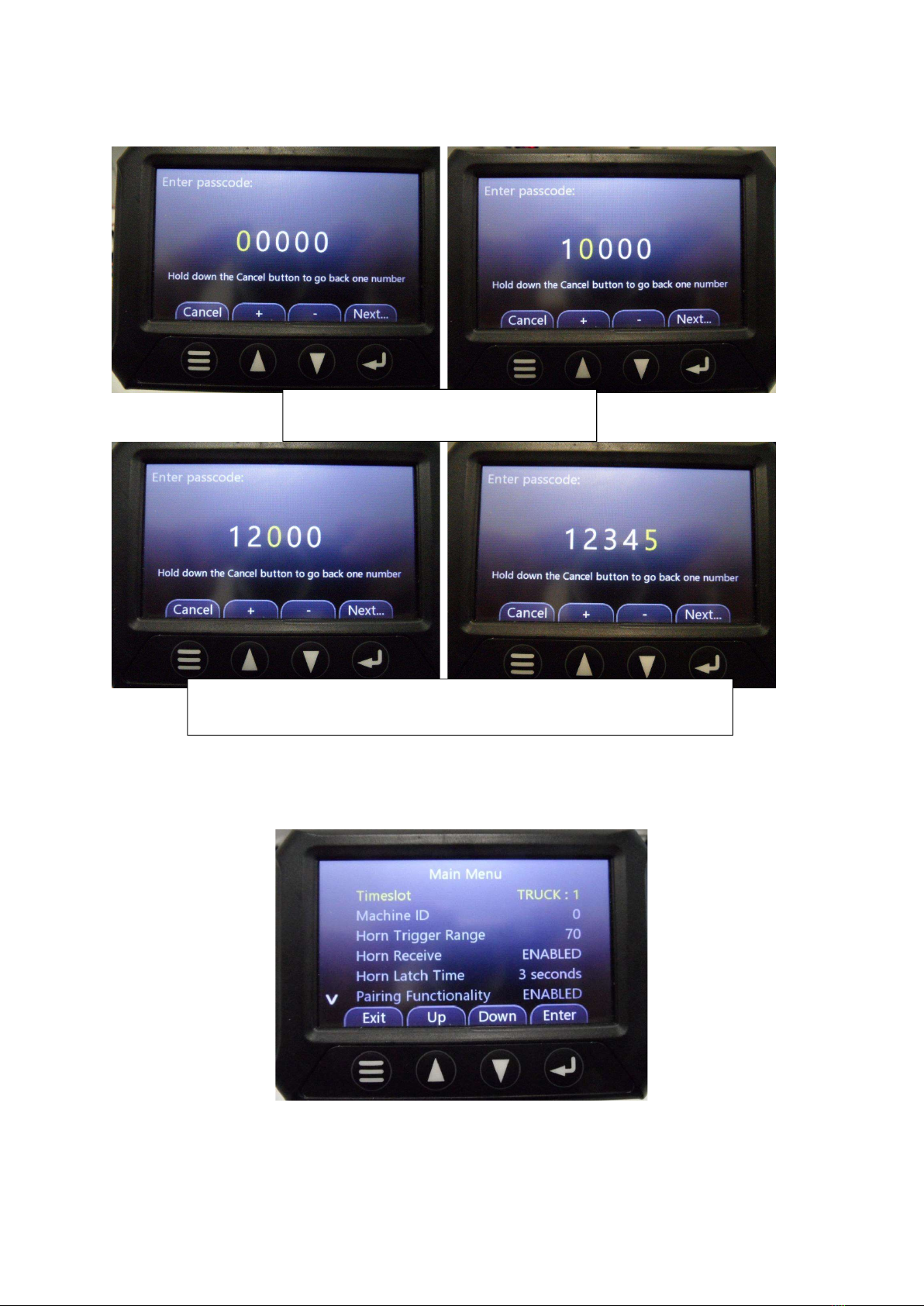
1.3.6 Follow the next screen shots to enter the configuration menu
1.3.9 If the entered password is correct, the configuration menu will be displayed. If the password
is incorrect, the display will re-start and the installer can press the menu button to try again.
Use the ‘up’ arrow and the ‘enter’ key to
enter the default password of ‘12345’
If you need to change a number you have already confirmed, hold down
the MENU key for 2 seconds to go back and edit the previous number.
Version 1.3 – 30/11/2017 8
1.4 CONFIGURATION MENU OPTIONS
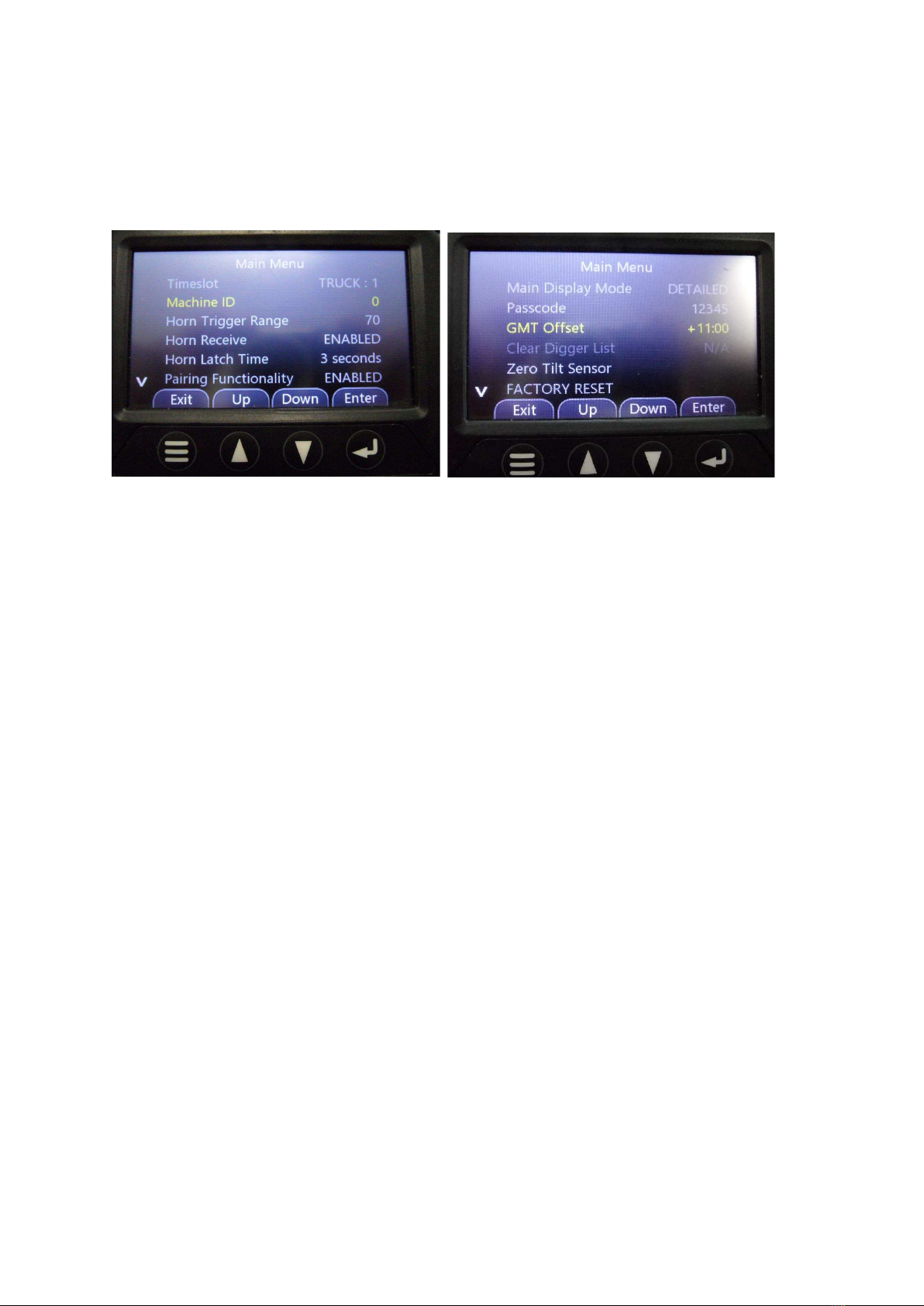
1.4.1 The options below will be visible when the configuration menu is accessed, use the ‘down’
arrow to scroll through the options.
Pressing the menu button at any time will save the settings and re-start the display. The following
list details what each configuration option does:
Timeslot: - Sets the mode, to make the display a Digger or Truck. By default, all displays are trucks.
1 – Truck timeslot. If this unit is being installed in a truck or a machine that needs to receive horn
presses, set the timeslot to 1.
2 – Digger timeslots. If this unit is being installed as a digger or a machine that needs to transmit
horn presses, select the timeslot 2.
Machine ID: - The ID is only compulsory for the diggers. A Machine ID can NEVER be set to ‘0’. Set
the machine ID by pressing the up and down keys, then press enter to go to the next number. For
example, to set the machine ID to 223, enter 0223 on the screen. It is imperative that no two
diggers ever share the same Machine ID as this will have the possibility to lock the entire system
up or give an erroneous horn trigger to the incorrect truck.
Horn Trigger Range: - The range in which the system will sound the horn if someone else within this
distance presses their horn. By default, this is set to 70m. The ranges available are from 20m – 250m
in 5m increments.
Horn Receive: - This sets if the unit can receive horn triggers from other diggers. If horn receive is
disabled, the unit will not receive any horn presses from diggers.
Horn Latch Time: - When a digger operator presses the horn button, the horn will be latched for the
time set here. This ensures that even if a digger operator presses the horn very quickly, the truck will
always receive a horn trigger. The default is 3 seconds.
Pairing Functionality: - Enabling the pairing functionality allows the ‘Pair’ menu to be shown on the
main screen. Operators will be able to select a digger to pair to. If pairing is disabled, the operator
will not be able to access any pairing functionality.
Version 1.3 – 30/11/2017 9
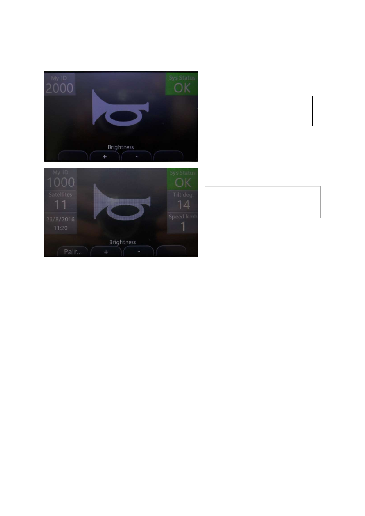
Main Display Mode: - The display can be set to two modes: Detailed and Simple:
GMT Offset: - Greenwich Mean Time offset, e.g. NSW is +11:00 in summer and +10:00 in winter.
Passcode: - Allows a qualified installer to set the menu passcode. Setting the passcode to zero will
disable the passcode completely. The default code is 12345.
Clear Digger List: - Clears the list of diggers in the Pairing menu.
Zero Tilt Sensor: - After the antenna is installed and the machine is on flat ground, selecting this
function will zero the tilt sensor built into the antenna. This is displayed on the ‘Detailed Display
Mode’
FACTORY DEFAULTS: Removes all settings and resets the software back to its factory defaults.
Simple
: Only the Machine ID and
System status are displayed on the
main screen.
Detailed
: The Machine ID, Satellites,
Time/date, System Status and Tilt are
displayed on the main screen.
Version 1.3 – 30/11/2017 10
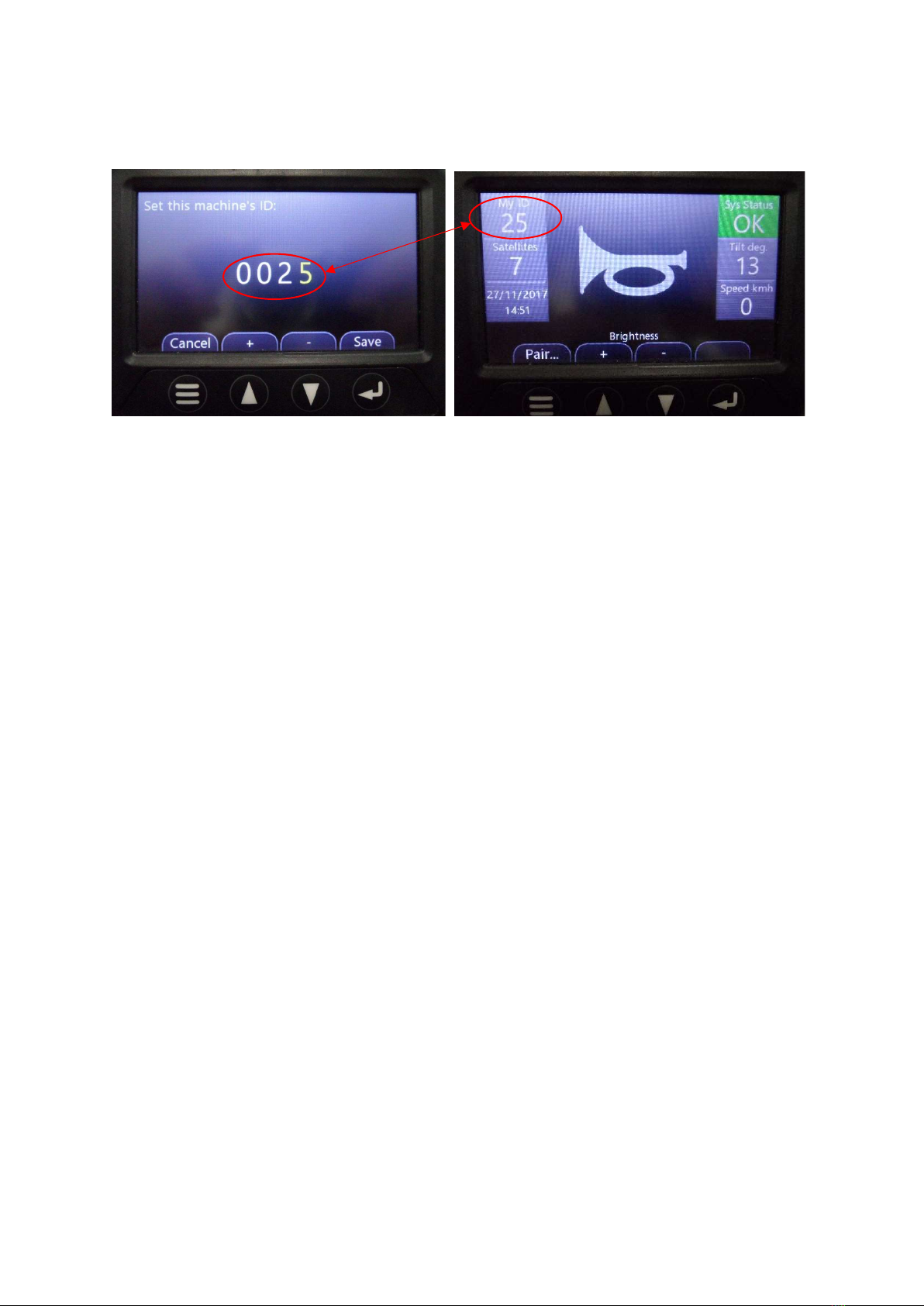
1.4.2 (OPTIONAL) To finish the installation and setup of the truck silent horn is to give the unit an
ID number that is assigned to the vehicle, in this example it is 25
The silent horn is now ready for use.
Inhaltsverzeichnis


