HVTest HTYWS-H Bedienungsanleitung
1
Dear Client
Thank you for Purchasing our HTYWS-H Electrolytic Oil
Moisture Analyzer. Please read the manual in detail prior to first
use, which will help you use the equipment skillfully.
Our aim is to improve and perfect the
company's products continually, so there may be
slight differences between your purchase equipment
and its instruction manual. You can find the changes
in the appendix. Sorry for the inconvenience. If you have further
questions, welcome to contact with our service department.
The input/output terminals and the test column
may bring voltage, when you plug/draw the test wire or
power outlet, they will cause electric spark. PLEASE
CAUTION RISK OF ELECTRICAL SHOCK!
Company Address:
T4,No. 41, High-tech 2 Road,East Lake High-tech Development Zone,
Wuhan
Sales Hotline: 86-27- 87457960
After Service Hotline:86-27- 87459656
Fax: 86-27- 87803129
E-mail: [email protected]
Website: www.hvtest.cc

2
SERIOUS COMMITMENT
All products of our company carry one year limited warranty
from the date of shipment. If any such product proves defective
during this warranty period we will maintain it for free. Meanwhile
we implement lifetime service. Except otherwise agreed by
contract.
SAFETY REQUIREMENTS
Please read the following safety precautions carefully to avoid
body injury and prevent the product or other relevant subassembly
to damage. In order to avoid possible danger, this product can only
be used within the prescribed scope.
Only qualified technician can carry out maintenance or repair
work.
--To avoid fire and personal injury:
Use Proper Power Cord
Only use the power wire supplied by the product or meet the
specification of this produce.
Connect and Disconnect Correctly
When the test wire is connected to the live terminal, please do
not connect or disconnect the test wire.
Grounding
The product is grounded through the power wire; besides, the

3
ground pole of the shell must be grounded. To prevent electric
shock, the grounding conductor must be connected to the ground.
Make sure the product has been grounded correctly before
connecting with the input/output port.
Pay Attention to the Ratings of All Terminals
To prevent the fire hazard or electric shock, please be care of
all ratings and labels/marks of this product. Before connecting,
please read the instruction manual to acquire information about the
ratings.
Do Not Operate without Covers
Do not operate this product when covers or panels removed.
Use Proper Fuse
Only use the fuse with type and rating specified for the product.
Avoid Touching Bare Circuit and Charged Metal
Do not touch the bare connection points and parts of energized
equipment.
Do Not Operate with Suspicious Failures
If you encounter operating failure, do not continue. Please
contact with our maintenance staff.
Do Not Operate in Wet/Damp Conditions.
Do Not Operate in Explosive Atmospheres.
Ensure Product Surfaces Clean and Dry.

4
-Security Terms
Warning: indicates that death or severe personal injury may
result if proper precautions are not taken
Caution: indicates that property damage may result if proper
precautions are not taken.

5
Content
I.Overview………………………………………………….…….3
II.Features………………………………………………………..3
III.Technical parameters…………………………..…………….4
IV.The structure and assembly of instrument…………..…….5
V.Working principle………………………………………..…….8
VI.Menu and key operation instructions………………...…….8
VII.Sample operation………………………………………….15
VIII.Maintenance………………………………………….……17
IX.Common troubleshooting………………………….………19

6
I.Overview
Carl - Philip Hugh coulomb titration method for accurate measuring moisture
content of samples, this method with the advantages of high precision, low
cost. Widely used in electric power, petroleum, chemical, pharmaceutical, food
and other industries.
Carl - Philip Hugh
II.Features
Instrument adopts a powerful new generation processors and peripheral
circuits, which with excellent low-power performance makes it possible to use
small battery power supply, and then achieve the portable function; measuring
electrode signal as a criterion of electrolysis end, its stability and accuracy is
the key factor affecting the measurement accuracy. The use of advanced
devices and methods can achieve the precise detection of measuring
electrode signal; with new software compensation correction algorithm to
improve the measurement accuracy; large-size LCD display with touch keys,
the display interface with curve is intuitive and friendly.
Main features:
1. Adopts 320x240 dot matrix LCD display, touch keys, friendly interface;
2. Using the electrolysis circuit of switch constant-current source, reduce
power consumption of the instrument;
3. High-precision measuring electrode signal and detection circuit can
determine the electrolysis end quickly and accurately, and with strong

7
anti-interference ability;
4. The use of blank current compensation and equilibrium point drift
compensation to correct the measurement results;
5. Measuring electrode signal show as a bar graph on the LCD screen
indicates water content of electrolyte intuitively;
6. Real-time depicts the curve of electrolysis speed changing with time during
electrolysis process, the user can monitor the process of electrolysis, and can
judge whether the electrolyte is ineffective according to the curve;
7. 10 gears stirring speed adjustment; auto electrolysis gains adjustment;
8. With measuring electrode open-circuit fault, short circuit fault automatic
detection functions;
9. Automatically store historical records, up to 100;
10. Calendar clock with temperature compensation is accurate, and can
automatically records the date and time of test; it can run more than 10 years
in the power-down state;
11. With USB interface, it is convenient to communicate with the computer.
III.Technical parameters
1. Accuracy:
Amount of electrolysis water Accuracy
10ug~1000ug ±2ug
>1000ug 0.2%
2. General electrical parameters:
Measurement range: 0ug-200mg
Resolution: 0.1ug
Maximum electrolytic speed: 40ug/s
Power supply voltage: AC220V±20%
Maximum power consumption: 30W
Ambient temperature: 10 ~ 35℃
Ambient humidity: ≤85%

8
Dimensions: 320×240×150(mm)
Net weight: 5kg
IV.The structure and assembly of instrument
1. Host
Figure 4-1 Host
⑴LCD screen and buttons ⑵Electrolytic cell
⑶Power switch ⑷Fuse
⑸Power outlet ⑹RS232 interface
⑺Electrolytic electrode interface ⑻Measuring electrode interfaces
⑼Electrolytic cell stent ⑽Mini printer
2. Electrolytic cell
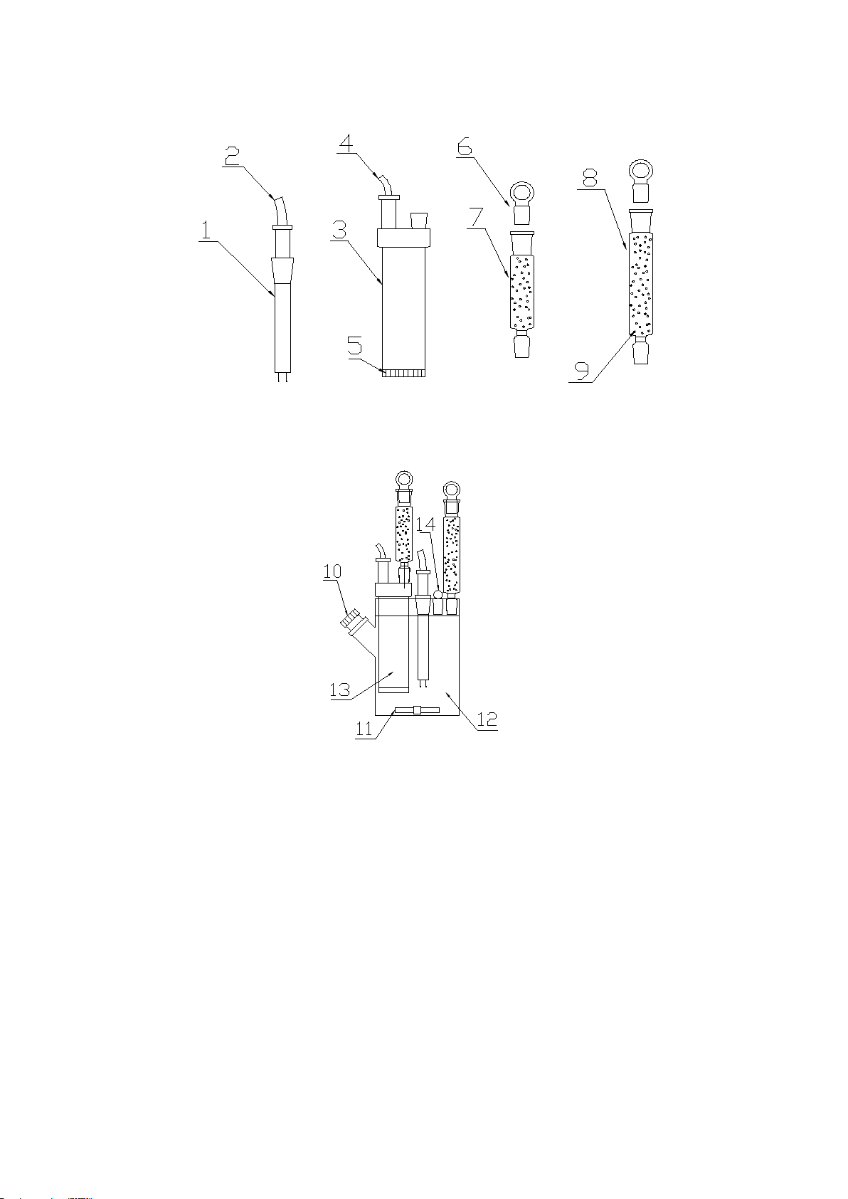
9
Figure 4-2 Decomposed diagram of electrolytic cell
Figure 4-3 Assembly diagram of electrolytic cell
⑴Measuring electrode ⑵Measuring electrode line
⑶Electrolytic electrode ⑷Electrolytic electrode line
⑸Ion filter membrane ⑹Glass stopper of drying tube
⑺Cathode chamber drying tube ⑻Anode chamber drying tube
⑼Silica gel (drier) ⑽Inlet
⑾Stir ⑿Anode chamber
⒀Cathode chamber ⒁Glass stopper of electrolytic cell
3. Assembly
⑴Put silica gel particles into the drying tube (Figure 4-2 7,8 shows)
10
Note: The piping of drying tube must maintain certain ventilation, cannot
be completely closed, or prone to danger!
⑵Put the milky white silica gel pad into stopcock, and use fastening bolt to
screw uniformly. (see Figure 4-4)
Figure 4-4 Assembly diagram of inlet stopper
⑶Put stir through the inlet into the electrolytic bottle carefully
⑷In the measuring electrode, electrolytic electrode, cathode chamber drying
tube, anode chamber drying tube, inlet stopcock grinding mouth ,evenly coat
with a layer of vacuum grease, after the above components into the electrolytic
bottle, gently rotate to let it seal well.
⑸Using a clean and dry funnel (or use change dispensers) inject 120-150 ml
electrolyte into the anode chamber of electrolytic cell from the seal of
electrolytic cell; Repeat process to inject electrolyte into the cathode chamber
of electrolytic cell; let the liquid height of electrolyte in the cathode chamber
and the anode chamber is the same. In the glass stopper of electrolytic cell
evenly coat with a layer of vacuum grease, gently rotate to let it seal well.
Note: it should be operated in good ventilation environment, do not
inhale or touch the reagents, if touch with the skin, rinse with water.
After completing the above steps, put the electrolytic cell into the electrolytic
cell stent (Figure 4-1, 9), then the electrolytic electrode line and the measuring
Silicone pad
Fastening bolt
Stopcock
Inhaltsverzeichnis
Andere HVTest Messgerät Handbücher

HVTest
HVTest SMG3000 Bedienungsanleitung

HVTest
HVTest SGB-C Series Bedienungsanleitung

HVTest
HVTest GM-5kV Bedienungsanleitung

HVTest
HVTest HTHL-200A Bedienungsanleitung

HVTest
HVTest GM-15kV Bedienungsanleitung

HVTest
HVTest HT-TC Bedienungsanleitung

HVTest
HVTest GM-10kV Bedienungsanleitung

HVTest
HVTest SMG2000B Bedienungsanleitung

HVTest
HVTest GM-20kV Bedienungsanleitung

HVTest
HVTest HTHL-100B Bedienungsanleitung


