
IBEX TS51C Bedienungsanleitung

ASSEMBLY GUIDE
TS51C Drum Mower

ASSEMBLY GUIDE
2022-1.1 IBEX EQUIPMENT CO. 1
TS51C Drum Mower
CONTENTS
Scope and Purpose ................................................................................................................. 3
Uncrating................................................................................................................................ 3
Hardware Guide......................................................................................................................... 4
PTO Guard Installation............................................................................................................ 4
Three Point Hitch.................................................................................................................... 3
Blade Installation.................................................................................................................... 4
Attaching the Drum Unit to the 3 Point Hitch......................................................................... 6
Transport Lock...................................................................................................................... 10
PTO Shafts ............................................................................................................................ 10
Pivot Restrictor..................................................................................................................... 12
Guard Installation................................................................................................................. 14
Safety Release (“Breakaway Bar”) ........................................................................................ 15
Lubrication ........................................................................................................................... 16
Figure 1 lifting the drum assembly............................................................................................. 3
Figure 2 hardware...................................................................................................................... 4
Figure 3 larger guard installed on the gearbox facing the tractor .............................................. 2
Figure 4 smaller guard with cut-out facing the rear (cutout may look different than picture) ... 2
Figure 5 the other small guard installed on the drum unit......................................................... 3
Figure 6 install the pins in the arms as shown............................................................................ 3
Figure 7 3 point hitch attached to tractor’s lift arms.................................................................. 4
Figure 8 plumb the 3 point hitch unit using the top link............................................................. 4
Figure 9 blade tool ..................................................................................................................... 5
Figure 10 installing a blade ........................................................................................................ 5
Figure 11 drum unit positioned in relation to the 3-point hitch frame....................................... 6
Figure 12 lift arm and swivel tee in place................................................................................... 6
Figure 13 lower lift arm in place................................................................................................. 7

ASSEMBLY GUIDE
2022-1.1 IBEX EQUIPMENT CO. 2
Figure 14 top spring arm installed with pin blocked up by using a 2x4 ...................................... 7
Figure 15 spring arm attachment to lower arm ......................................................................... 8
Figure 16 push the lower arm down to line up with drum unit.................................................. 8
Figure 17 pivot pin installed....................................................................................................... 9
Figure 18 storage stand ............................................................................................................. 9
Figure 19 transport lock........................................................................................................... 10
Figure 20 shaft with slip clutch end.......................................................................................... 11
Figure 21 connect the driveline with one-way clutch............................................................... 11
Figure 22 guard chains attached .............................................................................................. 12
Figure 23 pivot restrictor plate & handle installation............................................................... 13
Figure 24 pivot restrictor plate & handle shown installed from side....................................... 13
Figure 25 front guard has six holes .......................................................................................... 14
Figure 26 curtain straps secure to the guard frame ................................................................. 14
Figure 27 curtain installed with 2 holes for toe guard facing forward...................................... 15
Figure 28 safety release bar ..................................................................................................... 15
ASSEMBLY GUIDE
2022-1.1 IBEX EQUIPMENT CO. 3
SCOPE AND PURPOSE
This guide is limited to Ibex TS51C drum mowers (also labeled with the original manufacturer
model name, Galfre FR/G 130). The guide covers models manufactured in 2020 and forward.
This manual is a guide to aid in the assembly only. Consult the Quick Start Guide and User
Manual for instructions on usage and safety.
UNCRATING
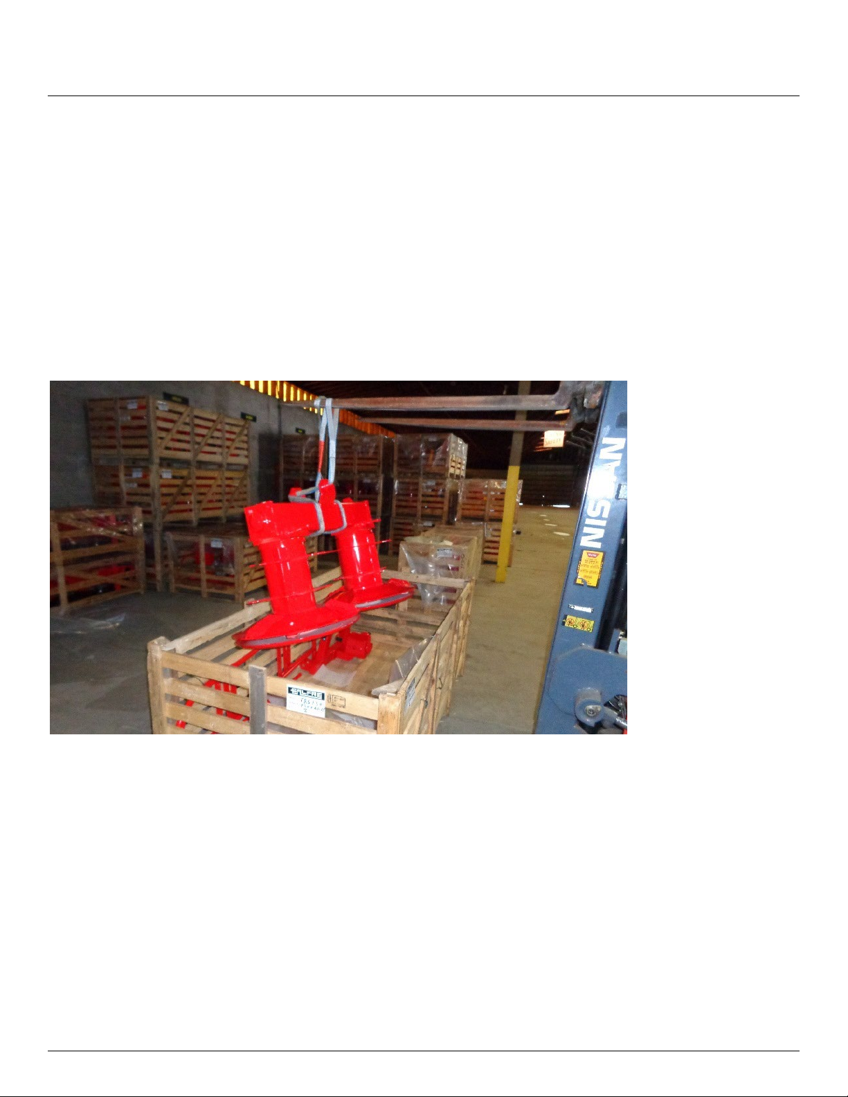
Heavier components can be lifted out of the crate, using lift straps or chains, if a lift is
available.
Figure 1 lifting the drum assembly
If no lift is available, the crate will need to be cut open for easier access. Remove the smaller
parts, then slide the drum unit out of the crate onto the ground. The drum mower bottom
skids drag across the ground during use, so it is alright to drag them to the location that you
plan to use for assembly. Lay out the parts so you can see everything in one place.
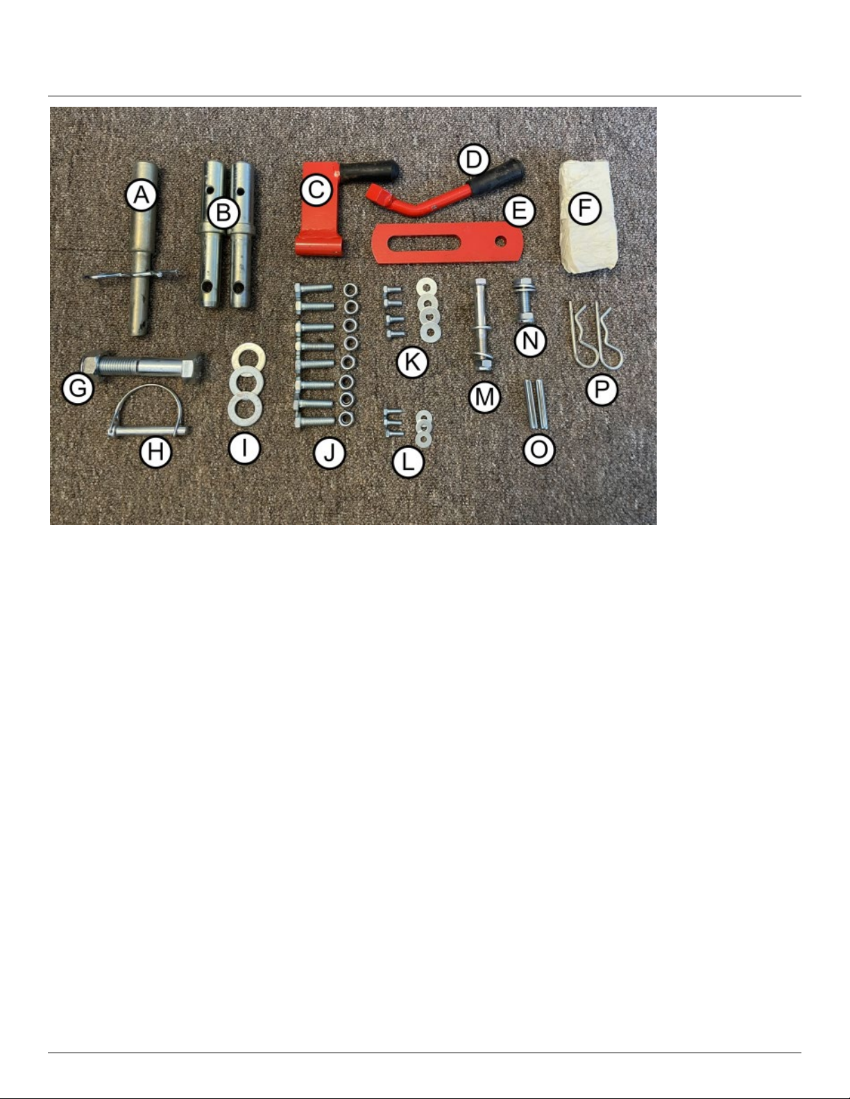
Take the bag of parts and sort them out in like groupings. It makes finding the hardware much
easier during assembly. Refer to Figure 2 and the subsequent list for hardware identification.
Note: Occasionally the manufacturer will pre-install some components and this may result in
your hardware assortment being slightly different than what is shown.
ASSEMBLY GUIDE
2022-1.1 IBEX EQUIPMENT CO. 4
Figure 2 hardware
Hardware Guide
A. Top link pin
B. 3-point hitch pins (Figure 6)
C. Transport lock (Figure 19)
D. Pivot restrictor handle (Figure 23)
E. Pivot restrictor plate (Figure 23)
F. Drum mower blades
G. Spring arm nut/bolt (Figure 15)
H. Stand retention clip (Figure 18)
I. Pivot restrictor handle washers (Figure 23)
J. Curtain frame nuts/bolts (Figure 25)
K. Hardware for large PTO guard (Figure 3)
L. Hardware for small PTO guard (Figure 5)
M. Hardware for transport lock (Figure 19)
N. Hardware for pivot restrictor plate (Figure 23)
O. Roll pins to retain 3 point hitch pins
P. R-clips to secure breakaway bar (Figure 28)
PTO GUARD INSTALLATION
Install the plastic PTO guards. They are easier to install before assembling the mower. Use the
set of 4 screws and washers provided in the hardware bag to install the larger guard on the
gearbox facing the tractor as shown in Figure 3. Note that this guard may appear somewhat
different, and may already be installed on the gearbox.

ASSEMBLY GUIDE
2022-1.1 IBEX EQUIPMENT CO. 2
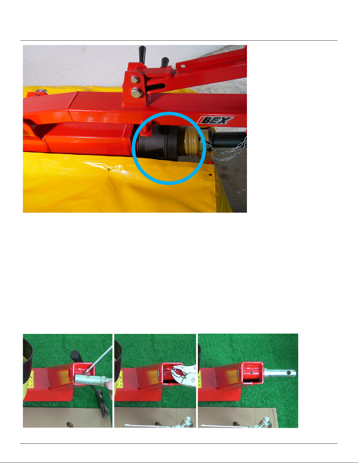
Figure 3 larger guard installed on the gearbox facing the tractor
The small guard with a cutout is installed on the 90 degree gearbox on the other side, with the
cutout facing the rear. This cutout provides space to allow the PTO shaft to pivot to 90 degrees
when the mower is switched to transport mode. This guard is normally already installed.
Figure 4 smaller guard with cut-out facing the rear (cutout may look different than picture)
Get the small guard without a cutout and use the set of 3 small screws and washers to install it
at the drum unit PTO connection as shown in Figure 5.
ASSEMBLY GUIDE
2022-1.1 IBEX EQUIPMENT CO. 3
Figure 5 the other small guard installed on the drum unit
THREE POINT HITCH
Find the two 3 point hitch pins (Figure 2, B) and the 2 smaller roll pins (Figure 2, O). The hitch
pins can be installed facing outward or inward to accommodate different lift arm widths, so
you may want to bring the hitch close to your tractor to see how it lines up before you decide
which position to install the pins.
Position the 3 point hitch so the two arms face up. Oil the holes in the pins and in the hitch,
and then oil the roll pin. Secure the roll pin with locking pliers and drive it through the holes
with a hammer.
Figure 6 install the pins in the arms as shown

ASSEMBLY GUIDE
2022-1.1 IBEX EQUIPMENT CO. 4
Attach the 3 point hitch to your tractor’s lift arms. You will need linchpins to secure them (not
included).
Figure 7 3 point hitch attached to tractor’s lift arms
Lift the 3 point hitch unit up and install the top link pin (Figure 2, A). Adjust the length of the
top link so that the 3 point hitch is plumb (straight up and down).
Figure 8 plumb the 3 point hitch unit using the top link
BLADE INSTALLATION
The six cutting blades that come with the mower are installed and changed with the blade
change tool. The blade change tool is stored on the top of the spring arm that connects the 3
point hitch to the drum unit, shown in Figure 9 fully assembled for identification.

ASSEMBLY GUIDE
2022-1.1 IBEX EQUIPMENT CO. 5
Figure 9 blade tool
To install a blade, position the blade change tool so that the two identical prongs are inserted
between the two discs of the drum, as seen in Figure 10. Raise the arm so that the pin of the
tool inserts into the slot on the upper disc. Pivot the tool up until there is sufficient clearance,
install the blade, and let the tool arm down. Be sure to install the blade so that its angled
edges are sloped downward. Once installed, be sure the blade is on the pin and swings freely.
Note that the drum unit may need to be raised to provide enough clearance to properly angle
the tool.
For safety purposes, never place your hand or fingers inside the opened space between the
discs.
Figure 10 installing a blade
ASSEMBLY GUIDE
2022-1.1 IBEX EQUIPMENT CO. 6
ATTACHING THE DRUM UNIT TO THE 3 POINT HITCH
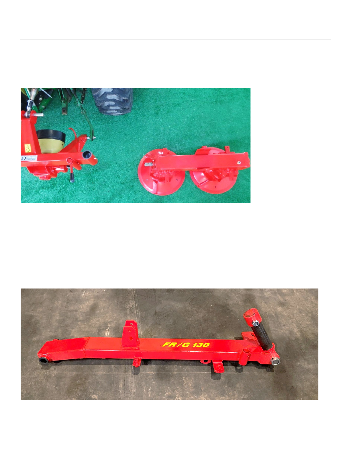
Place the drum unit so that it is oriented as shown in Figure 11. Be sure the PTO spline shafts
face each other.
Figure 11 drum unit positioned in relation to the 3-point hitch frame
To connect the 3 point hitch frame to the drum unit, first get the larger lift arm with a swivel
tee attached to it, shown in Figure 12. Remove the cap of the tee and place it on top of the
drum unit with the tee facing the 3 point hitch. Slide the tee into the 3 point hitch frame and
install the cap as shown in Figure 13, threading the nut only until you feel some resistance. The
nut will be removed later when mounting the top arm. Wait to attach the other end of the
lower arm until after the next step.
Figure 12 lower lift arm and swivel tee in place
Andere Handbücher für TS51C
3
Inhaltsverzeichnis
Andere IBEX Landwirtschaftliche Geräte Handbücher

IBEX
IBEX TS100 Bedienungsanleitung

IBEX
IBEX TM60 Gebrauchsanweisung

IBEX
IBEX TX40 Bedienungsanleitung

IBEX
IBEX TX80 Bedienungsanleitung

IBEX
IBEX TS130 Bedienungsanleitung

IBEX
IBEX TX40 Bedienungsanleitung

IBEX
IBEX TX31 Bedienungsanleitung

IBEX
IBEX TS51C Bedienungsanleitung

IBEX
IBEX TM67C Bedienungsanleitung

IBEX
IBEX TS106 Bedienungsanleitung


