
Icon Process Controls truflo TIB Series Bedienungsanleitung

TIB SERIES
TIB Series Battery Flow Meter

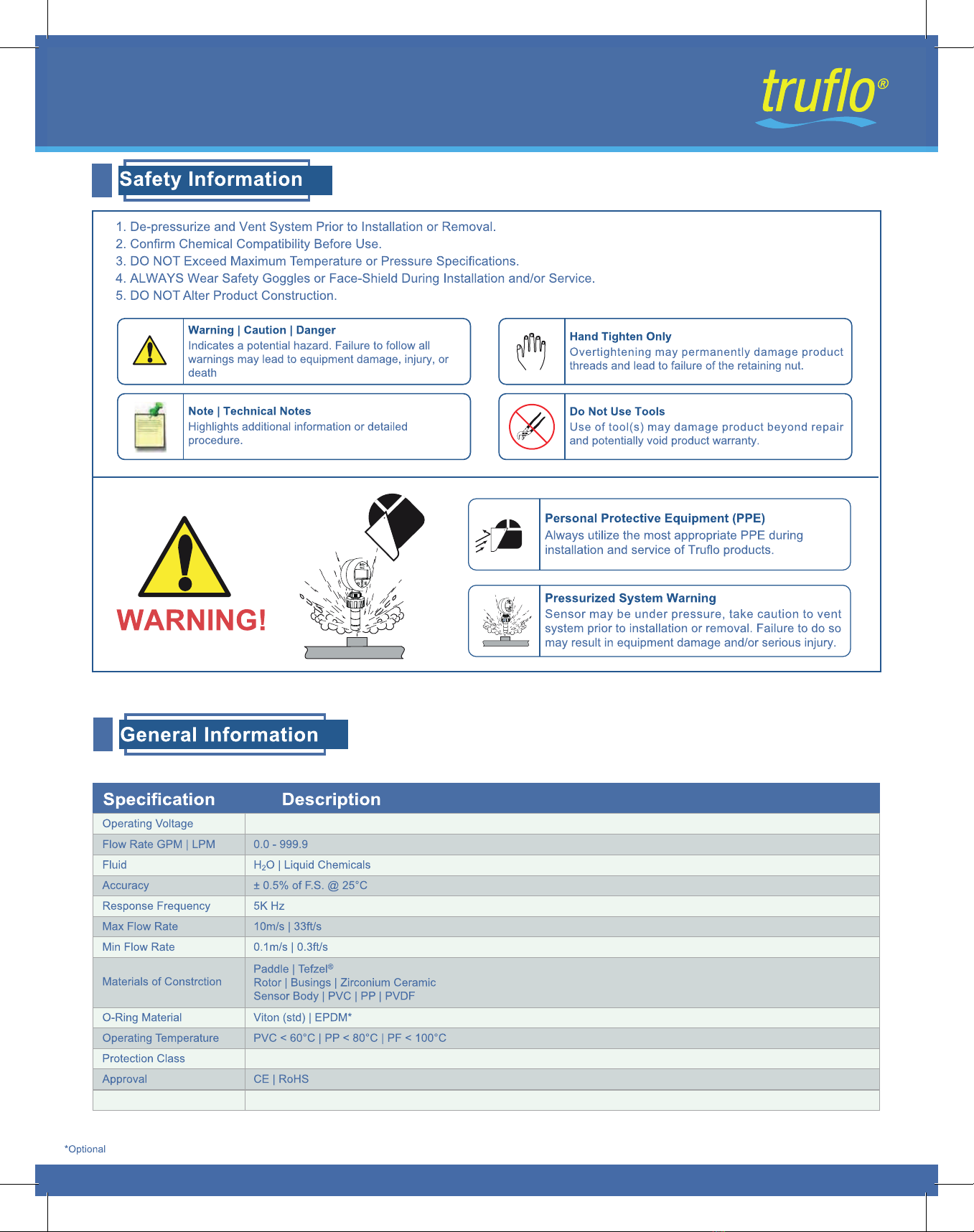
IMPORTANT!
When installing the sensor into the application, use the
retainer nut to thread in and tighten the flow meter. Do not
use the flow meter display to install the sensor.
The flow meter connection must be compatible with the
mating connection and must be assembled appropriately. If
the mating parts do not seal completely, a sealing material
may be considered.
IMPORTANT!
Flow Meters are not to be subject to water hammer or pressure spikes!
WARNING!
Before installation be certain the appropriate gauge has been selected considering operating pressure / full scale pressure /
proof pressure, wetted material requirements, media compatibility, operating temperature, vibration, pulsation, desired
accuracy and any other flow meter component related to the service application.
This includes the potential need for protective attachments and/or special installation requirements.
Failure to do so could result in equipment damage, sensor failure and/or personal injury. Only qualified personnel should be
permitted to install and maintain the pressure sensors
Read the User's Manual Carefully. Manufacturer Reserves the Right to Implement Changes Without Prior Notice.
'R1RW8Ve Display
To Tighten
IMPORTANT!
The flow sensor may be under pressure, it is very important
to ensure that the system has been vented prior to removal.
Failure to do so may result in equipment damage and/or
serious personal injury. ,
The flow meter connection must be compatible with the
mating connection and must be assembled appropriately. If
the mating parts do not seal completely, a sealing material
may be considered.
TIB SERIES
%DWWHU\2SHUDWHG3DGGOH:KHHO)ORZ0HWHU
9'&
%DWWHU\7\SH /LVR&O+LJK&DSDFLW\/LWKLXP_7,%+P$K_<UV_7,%9P$K_<UV
1(0$;_,3
03

Note: 'XULQJV\VWHPGHVLJQWKHVSHFLILFDWLRQVRIDOO
FRPSRQHQWVPXVWEHFRQVLGHUHG_1RQ6KRFN
7KH7,6HULHVLVHTXLSSHGZLWKD=LUFRQLXP&HUDPLF5RWRU3LQ
DQG%XVKLQJV7KH7,6HULHVDOVRLQFRUSRUDWHVDFRQWRXUHG
/RZ'UDJ3DGGOH:KHHOOHDGLQJWRUHGXFHGGUDJORQJHU
ZHDUDQGDKLJKHUDFFXUDF\
4 Blade ETFE (Tefzel®) Rotor
5H'HVLJQHG&RQWRXUHG3DGGOH
Integrated Solid State Electronics
(QFDSVXODWHGLQ(SR[\
Sensor Body
$YDLODEOHLQ39&_33_39')
6HQVRU/HQJWKVWR0HDVXUHWR3LSHV
Ceramic Rotor | Bushings
5RWRU
%XVKLQJV
&RQWRXUHG
3DGGOH
+LJK&KHPLFDO5HVLVWDQFH
/RQJ/LIH\HDUVPV
6HOI&OHDQLQJ'HVLJQ
Long Service Life Pressure vs. Temperature
T
KT
Se
rie
s
O
P
1F
T
MO
P
2G
P
M
TIB SERIES
%DWWHU\2SHUDWHG3DGGOH:KHHO)ORZ0HWHU
TIB Series
ECO GAL KL GPM LPM TPM
LTR
Flow RateFlow Rate
Battery Life
Mode of Operation
(Eco) = Extended Battery Life
r = FlowRate
3 Secs to view 6
Digits while
inTotalizer Screen
Highlighted to Indicated
Programmed Unit of Measurement
Display Functions
04
3 Secs to
change display
from Flow Rate
to Flow Total
Zirconium Ceramic Rotor Pin

Current Flow Rate | Total
0-1
Home Screen
Press & Hold &
1
Screen Lock
2
Programming Lock Out Feature
/&. 8QORFNHG: Factory Default
LCK= '1' Locked
3 sec
Press Key
0.1-9999
K Factor
3
Display Units
Press & Hold
1
Press
non | Eco
Display Mode
4
G63QRQ/('%DFN/LJKW_'HIDXOWLVVHWWRVHFV
G63(FRBack/ight )unction is not $ctive_([WHQGHG%DWWHU\/LIH
Press
Back Light Timer
5
Time on for Back Light _Secs
/RQJHU7LPH 6KRUWHU%DWWHU\/LIH
Press
Flow Alarm Delay
6
Press
Reset Totalizer
7
U(6(WFlow Totalizer Reset Disabled
U(6(W`'HIDXOWFlow Totalizer Reset Enabled
Press
Press to Select & Press To Confirm
)ORZ5DWH*30_/30_730
)ORZ7RWDO*$/_/75_./
Press Both Together for 3 Seconds
Press for 3 Seconds to Reduce Power Consumption
Totalizer Reset
Sleep Mode
Alarm Setup Press Both Together for 3 Seconds
Time Delay for Visual Alarm
3 sec
Press
Press
for Increase Value & Press for Decrease Value
to Change DigitV
9999
1-9999
Enter K Factor Value
6HH&KDUWRQ3DJHIRU.)DFWRU9DOXH
0-1
0
3URJUDPPLQJ
3URJUDPPLQJ'LVSOD\8QLWV
OPERATION
OPERATION
STEPS DISPLAY RANGE
STEPS DISPLAY RANGE
7,%SERIES
%DWWHU\2SHUDWHG3DGGOH:KHHO)ORZ0HWHU
6DYH9DOXH Press
05

0
7,%SERIES
%DWWHU\2SHUDWHG3DGGOH:KHHO)ORZ0HWHU
06
Min |Max Flow Rates
40.0 | 10.5 357.0 | 1350.02" | DN50
60.0 | 16.0 1850 | 3572 ½" | DN60
90.0 | 24.0 2800 | 7393" | DN80
125.0 | 33.0 4350 | 11494" | DN100
230.0 | 60.0 7590 | 19976" | DN150
315.0 | 80.0 10395 | 27358" | DN200
0.3m/s min. 10m/s max.
LPM |GPM LPM |GPM
Pipe Size

2XWOHW 2XWOHW 2XWOHW,QOHW
2XWOHW
[,' [,' [,' [,' [,' [,'
[,' [,' [,' [,'
*RRGLI1R
6HGLPHQW3UHVHQW
0D[LPXP6ROLGVZLWKSDUWLFOHVL]HQRWH[FHHGLQJPPFURVVVHFWLRQRUOHQJWK
*RRGLI1R$LU
%XEEOHV3UHVHQW
3UHIHUUHG,QVWDOODWLRQLI6HGLPHQW
RU$LU%XEEOHVPD\EH3UHVHQW
)LJXUH )LJXUH )LJXUH
2XWOHW,QOHW
[,' [,'
'HYHORSHG7XUEXOHQW)ORZ
9HORFLW\
3URILOH
)ORZ
7,6HULHV)ORZ0HWHUVPHDVXUHOLTXLGPHGLDRQO\7KHUHVKRXOGEHQRDLU
EXEEOHVDQGWKHSLSHPXVWDOZD\VUHPDLQIXOO7RHQVXUHDFFXUDWHIORZ
PHDVXUHPHQWWKHSODFHPHQWRIWKHIORZPHWHUVQHHGVWREHDGKHUHG 7KLV
UHTXLUHVDVWUDLJKWUXQSLSHZLWKDPLQLPXPQXPEHURISLSHGLDPHWHUVGLVWDQFH
XSVWUHDPDQGGRZQVWUHDPRIWKHIORZVHQVRU
,QOHW
&RUUHFWLRQ6HQVRU,QVWDOODWLRQ3RVLWLRQ
,QVWDOODWLRQ3RVLWLRQV
[(OERZ
)ODQJH
,QOHW
5HGXFHU
(OERZ'RZQZDUG)ORZ (OERZ'RZQZDUG)ORZ8SZDUG %DOO9DOYH
,QOHW ,QOHW
2XWOHW
7,%SERIES
%DWWHU\2SHUDWHG3DGGOH:KHHO)ORZ0HWHU
07

ICON ™
PROCESS CONTROLS
Corros ion -Free
Instrumen tat ion Equ ipm ent
Manufacturer Reserves the Right to Implement Changes Without Prior Notice.
IMPORTANT!
When installing the gauge connection into the
application, use the wrench area to thread in and tighten
the gauge. Do not use the gauge case to install the
gauge.
This could result in loss of accuracy, excessive friction, or
mechanical damage to the pressure element or gauge
case. The gauge connection must be compatible with the
mating connection and must be assembled appropriately. If
the mating parts do not seal completely, a sealing material
may be considered.
IMPORTANT!
Gauges are not to be subject to water hammer or pressure spikes!
WARNING!
Before installation be certain the appropriate gauge has been selected considering operating pressure / full scale pressure /
proof pressure, wetted material requirements, media compatibility, operating temperature, vibration, pulsation, desired
accura-cy and any other gauge component related to the service application (including the potential need for protective
attachments and/or special installation requirements). Failure to do so could result in equipment damage, gauge failure and/or
personal
ICON ™
PROCESS CONTROLS
Corros ion -Free
Instrumen tat ion Equ ipm ent
Do Not Use Display to Tighten
Hand Tighten Using the Retention Cap
Manufacturer Reserves the Right to Implement Changes Without Prior Notice.
IMPORTANT!
When installing the gauge connection into the
application, use the wrench area to thread in and tighten
the gauge. Do not use the gauge case to install the
gauge.
This could result in loss of accuracy, excessive friction, or
mechanical damage to the pressure element or gauge
case. The gauge connection must be compatible with the
mating connection and must be assembled appropriately. If
the mating parts do not seal completely, a sealing material
may be considered.
IMPORTANT!
Gauges are not to be subject to water hammer or pressure spikes!
WARNING!
Before installation be certain the appropriate gauge has been selected considering operating pressure / full scale pressure /
proof pressure, wetted material requirements, media compatibility, operating temperature, vibration, pulsation, desired
accura-cy and any other gauge component related to the service application (including the potential need for protective
attachments and/or special installation requirements). Failure to do so could result in equipment damage, gauge failure and/or
personal
Ensure Silicone Grease* is Applied
to O-Rings Prior to Insertion into Fitting
*Ensure Silicone Grease is Suitable for Application

0
TIB SERIES
%DWWHU\2SHUDWHG3DGGOH:KHHO)ORZ0HWHU
'R1RW8VH
'LVSOD\WR7LJKWHQ
+DQG7LJKWHQ8VLQJ
WKH5HWHQWLRQ&DS
Hand Tighten Retention Cap } Do Not
Use Display
Display Rotates 330 Degrees
Do Not Use Display to Tighten
09
0
SERIES
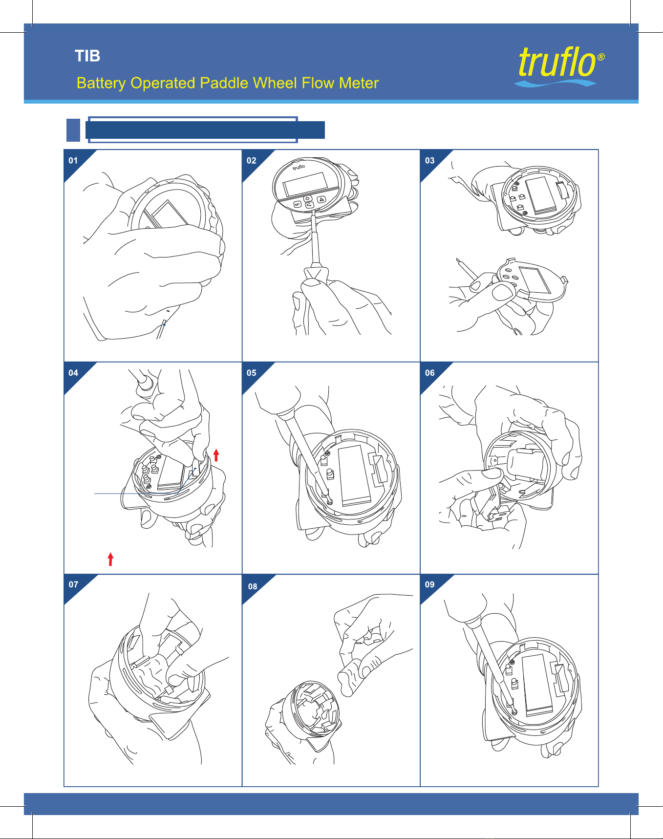
Battery Replacement | V Series
Battery
Remove Polycarbonate Lid
Remove Screws
Remove 1st Battery
Insert Screw Driver into SlotRemove Cover
Carefully Remove Display Module
Remove Battery Pack Replace Battery PackReassemble
10
TIB Series
TIB SERIES
Dieses Handbuch passt für folgende Modelle
2
Inhaltsverzeichnis
Andere Icon Process Controls Messgerät Handbücher

Icon Process Controls
Icon Process Controls truflo TK Series Bedienungsanleitung

Icon Process Controls
Icon Process Controls truflo Ultraflo UF500 Bedienungsanleitung

Icon Process Controls
Icon Process Controls Truflo TKB Series Gebrauchsanweisung

Icon Process Controls
Icon Process Controls truflo UltraFlo 2000 Series Bedienungsanleitung

Icon Process Controls
Icon Process Controls Level Pro UltraPro 500 Series Bedienungsanleitung


