
IET Labs SRC-10T-Tnetwork Fehlerbehebungshandbuch

¨PRECISION INSTRUMENTS FOR TEST AND MEASUREMENT ¨
Email: inf[email protected]
TEL: (516) 334-5959 • FAX: (516) 334-5988
www.ietlabs.com
IET LABS, INC.
SRC-Tnetwork
Resistance Standard
User and Service Manual
Copyright © 2022 IET Labs, Inc.
Visit www.ietlabs.com for manual revision updates
SRC-100T-Tnetwork im/August 2022

¨PRECISION INSTRUMENTS FOR TEST AND MEASUREMENT ¨
Email: inf[email protected]
TEL: (516) 334-5959 • FAX: (516) 334-5988
www.ietlabs.com
IET LABS, INC.

WARRANTY
We warrant that this product is free from defects in material and workmanship and, when properly used,
will perform in accordance with applicable IET speci•cations. If within one year after original shipment,
it is found not to meet this standard, it will be repaired or, at the option of IET, replaced at no charge when
returned to IET. Changes in this product not approved by IET or application of voltages or currents greater
than those allowed by the speci•cations shall void this warranty. IET shall not be liable for any indirect,
special, or consequential damages, even if notice has been given to the possibility of such damages.
THIS WARRANTY IS IN LIEU OF ALL OTHER WARRANTIES, EXPRESSED OR IMPLIED,
INCLUDING BUT NOT LIMITED TO, ANY IMPLIED WARRANTY OF MERCHANTABILITY OR
FITNESS FOR ANY PARTICULAR PURPOSE.
i

ii
Safety Symbols
General de•nitions of safety symbols used on the instrument or in manuals are listed below.
Caution symbol: the product is marked with this symbol when it is necessary for the user to
refer to the instruction manual.
Hazardous voltage symbol: the product is marked with this symbol when high voltage maybe
present on the product and an electrical shock hazard can exist.
Indicates the grounding protect terminal, which is used to prevent electric shock from the
leakage on chassis. The ground terminal must connect to earth before using the product
Direct current.
Alternating current.
Frame or chassis terminal. A connection to the frame (chassis) of the equipment which
normally includes all exposed metal structures.
On supply.
O• supply.
Hot surface. Avoid contact. Surfaces are hot and may cause personal injury if touched.
Disposal
Waste Electrical and Electronic Equipment (WEEE) Directive 2002/96/EC
This product complies with the WEEE Directive (2002/96/EC) marking requirements.
The a!xed label indicates that you must not discard this electrical/ electronic product in domestic
household waste.
Product Category: With reference to the equipment types in the WEEE directive Annex 1, this product
is classi•ed as a “Monitoring and Control instrumentation” product.
Do not dispose of electrical appliances as unsorted municipal waste, use separate collection facilities.
Contact your local government for information regarding the collection systems available. If electrical
appliances are disposed of in land•lls or dumps, hazardous substances can leak into the groundwater
and get into the food chain, damaging your health and well-being.
When replacing old appliances with new one, the retailer is legally obligated to take back your old ap-
pliances for disposal.
Proposition 65 Warning for California Residents
WARNING: Cancer and Reproductive Harm - www.P65Warnings.ca.gov.
This product may contain chemicals known to the State of California to cause cancer, birth defects, or
other reproductive harm

iii
SAFETY PRECAUTIONS
The following general safety precautions must be observed during all phases of operation, service,
and repair of this instrument. Failure to comply with these precautions or with speci•c WARNINGS
elsewhere in this manual may impair the protection provided by the equipment. Such noncompliance
would also violate safety standards of design, manufacture, and intended use of the instrument.
IET Labs assumes no liability for the customer’s failure to comply with these precautions.
This is an indoor use product.
DANGEROUS PROCEDURE WARNINGS
Comply with all WARNINGS - Procedures throughout in this manual and instructions on the
instrument prevent you from potential hazard. These instructions contained in the warnings must
be followed.
BEFORE APPLYING POWER
Verify that all safety precautions are taken. Make all connections to the instrument before applying
power. Note the instrument’s external markings described under “Safety Symbols”.
• DO NOT Operate in an Explosive Atmosphere
• Do not operate the instrument in the presence of inflammable gasses or fumes
• Operation of any electrical instrument in such an environment clearly constitutes a safety
hazard
• Use Caution around live circuits and whenever hazardous voltages > 45 V are present
• Operators must not remove instrument covers
• Component replacement and internal adjustments must be made by qualified maintenance
personnel only
• DO NOT substitute parts or modify the instrument
• When working with high voltages; post warning signs, train personnel and keep unauthorized
personnel away.
To avoid the danger of introducing additional hazards, do not install substitute parts or perform
unauthorized modifications to the instrument.
Return the instrument to an IET Labs for service and repair to ensure that safety features are maintained
in operational condition.
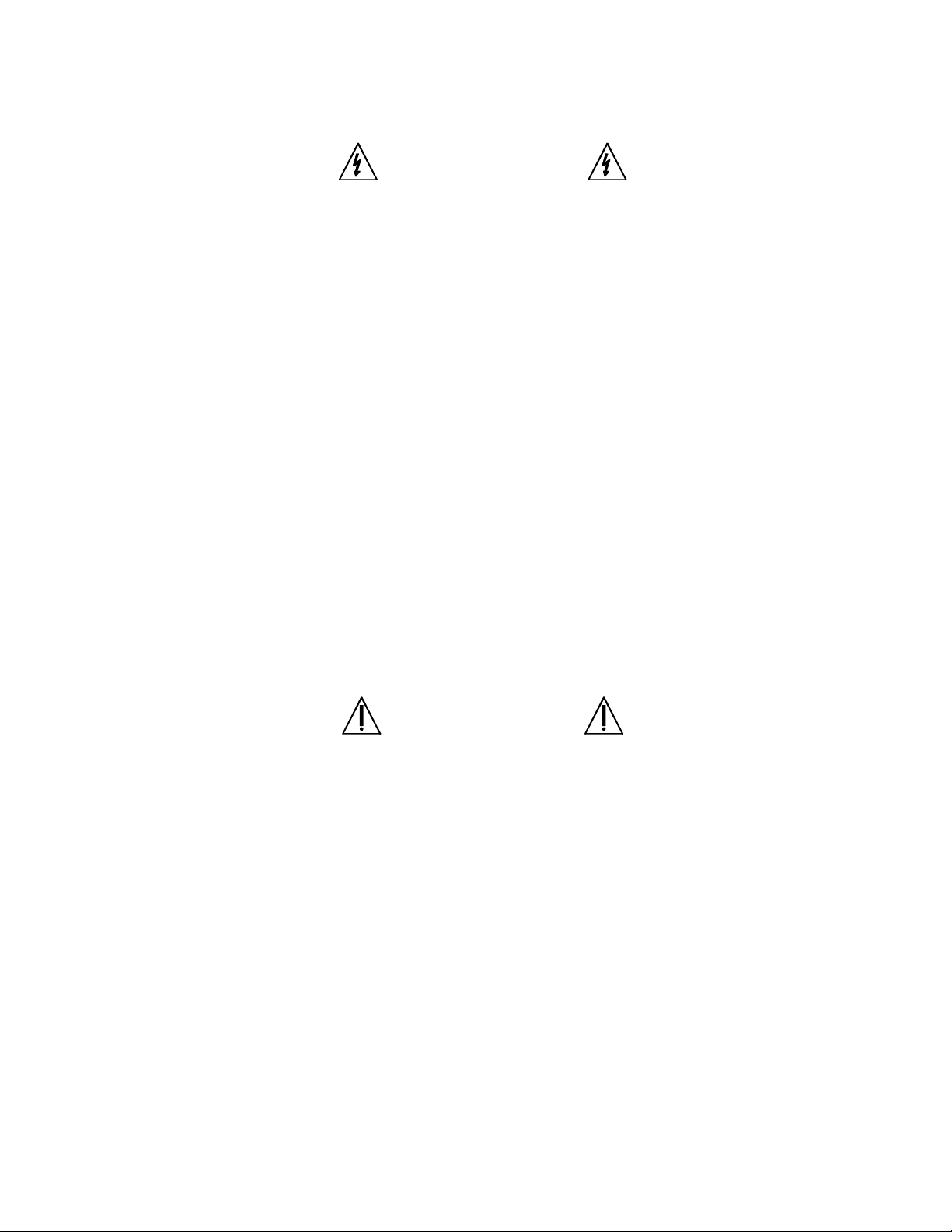
WARNING
OBSERVE ALL SAFETY RULES
WHEN WORKING WITH HIGH VOLTAGES OR LINE VOLTAGES.
Dangerous voltages may be present inside this instrument. Do not open the case
Refer servicing to qualified personnel
HIGH VOLTAGES MAY BE PRESENT AT THE TERMINALS OF THIS INSTRUMENT
WHENEVER HAZARDOUS VOLTAGES (> 45 V) ARE USED, TAKE ALL MEASURES TO
AVOID ACCIDENTAL CONTACT WITH ANY LIVE COMPONENTS.
USE MAXIMUM INSULATION AND MINIMIZE THE USE OF BARE
CONDUCTORS WHEN USING THIS INSTRUMENT.
Use extreme caution when working with bare conductors or bus bars.
WHEN WORKING WITH HIGH VOLTAGES, POST WARNING SIGNS AND
KEEP UNREQUIRED PERSONNEL SAFELY AWAY.
CAUTION
DO NOT APPLY ANY VOLTAGES OR CURRENTS TO THE TERMINALS OF THIS
INSTRUMENT IN EXCESS OF THE MAXIMUM LIMITS INDICATED ON
THE FRONT PANEL OR THE OPERATING GUIDE LABEL.
iv

Contents
Chapter 1 Introduction .................................................................................1
1.1 Introduction...............................................................................................1
Chapter 2 Specifications ..............................................................................3
Specifications ...................................................................................................3
Label .................................................................................................................4
Chapter 3 Operation ....................................................................................5
3.1 Initial Inspection and Setup ...................................................................... 5
3.2 Connections.............................................................................................. 5
3.3 Thermal emf Considerations.....................................................................5
3.4 Environmental Conditions......................................................................... 5
3.4.1 Operating Temperature ................................................................... 5
3.4.2 Storage Temperature.......................................................................5
3.5 Shipping and Handling ............................................................................. 5
Chapter 4 Maintenance................................................................................7
4.1 Maintainability and Reliability ...................................................................7
4.2 Preventive Maintenance ........................................................................... 7
4.3 Calibration ................................................................................................7
4.3.1 Calibration Interval ..........................................................................7
4.3.2 General Considerations ..................................................................7
4.3.3 Required Equipment .......................................................................8
4.3.4 Calibration Procedure .....................................................................8
v

vi

1
SRC-Tnetwork
1Introduction
Chapter 1
INTRODUCTION
1.1 Introduction
The SRC-Tnetwork is a standard resistor de-
signed for calibration of various electrometers and
megohmmeters.
The SRC-Tnetwork is a high resistance standard
that uses 3 lower value resistors configured in a T
network to create a higher resistance.
1.2 T-Networks
For high resistance measurements a T-network is
often used with instruments such as electrometers
and megohmmeters equipped with a guard termi-
nal.
A T-network uses low value resistors to achieve
what electronically looks like a high value resistor.
The basic operation of a T-network is three resis-
tors are place in a T configuration and connected
to the positive, negative and guard terminals of the
megohmmeter.
The ratio of the resistors then determines the effec-
tive resistance value that will actually be displayed
by the megohmmeter.
The advantages of the T network is that low value
resistors are used that can be easily and accurately
measured as compared with trying to calibrate a
single high value resistor.
This technique is used quite often in calibration
where it is difficult to accurately calibrate a resistor.
A T-network is illustrated in Figures 1.2 and 1.2
along with the formula to calculate the effective
resistance.
Guard
Positive Negative
R1
R2
R3
It In
Ig
Effective R = R1 + R2 R3
R2 R3 *R3
Figure 1.1: T-Network Model
Figure 1.2 illustrates an example T-network com-
prised of two 1 GΩ resistors and a single 10 kΩ
resistor to create a T-network that has an effective
resistance of 100 TΩ.
Figure 1.2: T-Network Example

2
SRC-Tnetwork
2 Specifications
Figure 1-1: SRC-Tnetwork Standard Resistor
100 TW
RESISTANCE STANDARD
MODEL SRC-100T T-network
SOURCE OUTPUT
CENTER TAP
GUARDGND
Dieses Handbuch passt für folgende Modelle
3
Inhaltsverzeichnis
Andere IET Labs Messgerät Handbücher

IET Labs
IET Labs LOM-510A Bedienungsanleitung

IET Labs
IET Labs 1409 Series Bedienungsanleitung

IET Labs
IET Labs 1433 Series Fehlerbehebungshandbuch

IET Labs
IET Labs 1565-E Fehlerbehebungshandbuch

IET Labs
IET Labs HACS-Z-A-6E-1pF Fehlerbehebungshandbuch

IET Labs
IET Labs SCA Series Bedienungsanleitung

IET Labs
IET Labs 1910 Fehlerbehebungshandbuch

IET Labs
IET Labs DE-5000 Fehlerbehebungshandbuch

IET Labs
IET Labs PRS-202 Series Bedienungsanleitung

IET Labs
IET Labs RS-925D Fehlerbehebungshandbuch


