IFR COM-120B Merkblatt

Rev. 1.0 Page 1

Rev. 1.0 Page 2

Rev. 1.0 Page 3
Thank you for taking the time to evaluate the IFR COM-120B. We know
that your time is valuable, so we have included a demonstration kit
complete with all of the accessories that you will need to evaluate the
advanced features of the COM-120B.
This instrument is also supplied with a step by step procedure to lead
you through the evaluation. In addition to the procedure, this instrument
has been configured with a software application that will configure the
equipment for each experiment.
Please use this guide and software, as it will allow you to rapidly see
many of the advanced features offered by the COM-120B in a minimal
amount of time.
The Operators guide and Programmers manual are also included if you
would like to gain even more detailed information.
We invite you to contact our Tech Support group techsupport@ifrsys.com to
receive a handy guide, the “RF DATAMATE” which provides much
useful information for anyone working in the wireless industry. Just drop
them a line and include your shipping information and one will be sent to
you.
If you have any suggestions or comments to improve this procedure or if
we have left something out, please drop us a line and we will try to
implement the addition or change if possible.
EMAIL requests to:
TO: info@ifrsys.com
Subject: RTS Evaluation
Thank you again for taking the time to evaluate the IFR COM-120B.

Rev. 1.0 Page 4
!RF Inputs and Outputs
!Audio Inputs and Outputs
!Rear Panel
!Basic Operation / Navigation
!Using the SETUP software
!Transmitter Testing
!Power
!Frequency
!Voice Deviation
!Scope Peak/Min Hold
!Tone Decoding
!CTCSS / DCS tone decode
!CTCSS / DCS tone deviation
!DTMF Decode
!Transmitter Distortion
!Receiver Testing
!Sensitivity
!Audio Output Power
!Cross-band Duplex
!Spectrum Analyzer
!Filter Tuning
!Cable Fault
!Return Loss
If you need assistance or have any questions about the COM-120B or performing any of the experiments
in this guide, do not hesitate to call our toll free number: (800) 835-2352 and select menu item 1. You
will be able to speak to a trained specialist who is well versed with this product.

Rev. 1.0 Page 5
Off the Air
Transmitter
connection
Full Duplex
Testing
Receiver
Half-Duplex
testing
+13 dBm
Tracking
Generator
Output
Transmitter
Input
Up to 50
Watts
Continuos
The Antenna port is designed for low
level off-the-air signals but has input
protection for up to 10 Watts in case of
accidental connection to transmitter.
Rev. 1.0 Page 6
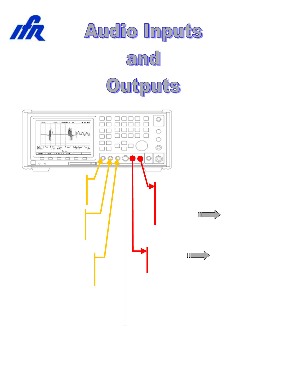
External Mod
source for radio
under test
Scope / DVM Input
(200 VRMS Max)
AUDIO / DATA
SINAD IN
(15mV – 15V)
EXT MOD IN
2 kHz / Vpk Narrow
10 kHz / Vpk Wide
DEMOD
OUT
AUDIO / DATA
GEN OUT
0 – 1.7 VRMS
External Audio
Analysis
Microphone
Input

Rev. 1.0 Page 7
RS-232 Serial I/O
Direct pin to pin
connection to PC
10 MHz Ext.
Reference Input
Optional
GPIB
Interface
Battery
Compartment
Replaceable
Battery
(Carry a Spare)
Ext. DC
Input
12-30 VDC
Master Power
Switch
LID / Storage Unit
AC Line Cord
DC Line Cord
Antenna
Fuses
Extra room for cables and connectors

Rev. 1.0 Page 8
For the purpose of demonstration, this demo unit has been configured
with software to perform specific setups that coincide with this
document. A description of the test setup is also provided. For
maximum benefit, a kit has been included to allow testing of a radio,
tuning of a filter and measurement of return loss.
The COM-120B provides a powerful set of insturments to allow repair,
calibration and diagnostic evaluations of communications systems. The
COM-120B organizes test functions into screens that can be selected
and altered to perform specific tests. A powerful memory system allows
storage and recall of test setups, frequency lists and test software for
quick evaluation.
Primary Screens:
GEN Test Receivers
REC Test Transmitters
DPLX Simultaneous Transmitter / Receiver test
SPCL Access optional Trunking Features and Tests
Memory Functions:
STORE Store and Label a test setup
RCL Recall a stored test setup
SHOW LIST Access test software

Rev. 1.0 Page 9
1. Remove the connector kit from the Evaluation Kit and Connect the N-
BNC adapter to the COM-120B’s T/R RF IN/OUT connector located
in the lower left corner of the instrument.
2. Remove the TNC-BNC adapter from the Evaluation Kit and connect
the COM-120B’s Antenna Input located in the upper right corner of
the instrument.
3. Connect the AC Line cord to the COM-120B’s rear panel receptical
and apply power with the power switch located in the lower left corner
of the instrument.
The COM-120B will begin it’s power on sequence followed by a selftest.
The Selftest can be aborted by pressing a mode key such as [REC].
The COM-120B should be preset to factory
default conditions prior to performing any of
the following procedures. To do this, press
the [SETUP] key to access the system
setup screen.
Press the down arrow key until item 12 is
selected as indicated by the cursor box.
Press the [ENTER] key to activate Factory
Defaults.

Rev. 1.0 Page 10
Basic Operation and Navigation
This guide will provide some basic operational knowledge to allow
configuration of the COM-120B but you should consult the Operators
Guide for more detailed information.
Begin by selecting a test mode of operation. Press the
[REC] key now to enable the Transmitter Test screen.
Screen settings are accomplished by positioning a
cursor to a field label and establishing the desired
setting. The cursor can be moved to a different field
through use of the 4 arrow keys on the COM-120B’s
front panel. These keys are located to the left of the
large knob in the DATA SCROLL section of the front
panel.
Changing Numeric fields:
To change the value of a numeric field such
as the RF frequency:
1. Position the cursor the field label (RF).
2. Use the numeric keypad to directly enter
the frequency and terminate entry by
pressing the [ENTER] key.
OR
3. Press the [ENTER] key to highlight the
frequency field.
4. Use the left or right arrow keys to position the cursor to the digit to be
changed and use the up and down arrows or the knob to adjust the
value of the selected digit. Terminate the entry with the [ENTER]
key.
Other Field types:
Another type of field allows selection of an item by list or menu. The
INPUT field (located just below the RF Frequency field) is an example of
this type. Position the cursor to the INPUT field and press the [ENTER]
key. With the field highlighted, press the up or down arrow key to cycle
through the available list of selections. Set this field to TR and terminate
the entry with the [ENTER] key.
Cursor
Function Keys F1 – F6
Andere Handbücher für COM-120B
1
Inhaltsverzeichnis
Andere IFR Messgerät Handbücher


