IN-COMMAND NCSP35CM Bedienungsanleitung

™
™
Patent # US 9,679,735
RV CONTROL AND MONITORING SYSTEM
NCSP35CM
Installation and Operation Manual (English)
NCSP35CM NCSP3DCCT


NCSP35CM
Read the iN-Command Manual, and these warnings and instructions carefully before using this product. Failure to follow the use
instructions in this owner’s manual, or improper use of the Mobile Application, Display Commander and/or Body Control Module, could
result in personal injury, including death.
Do not operate while vehicle is being driven.
The Mobile Application, Display Commander and/or Body Control Module should not be used while the vehicle is being driven. Use of
the Mobile Application, Display Commander and/or Body Control Module while the vehicle is being driven is dangerous and may cause
personal injury or property damage.
For adult use only.
The Mobile Application, Display Commander and Body Control Module are intended for adult use only, and are not to be used by persons
under the age of 18. Use by children may cause personal injury or property damage.
Operate only when you have a clear line of sight.
Do not operate any moving parts (including, but not limited to, awnings, jacks and slides), unless you have a clear line of sight to the
moving part. The Mobile Application, Display Commander or Body Control Module may be used only if you are giving instructions to,
and receiving instructions from, another person at least age 18 or older who can clearly see the moving part. Failure to follow these
instructions may result in serious personal injury or property damage.
Do not operate under the inuence of alcohol or drugs.
Do not operate the Mobile Application, Display Commander or Body Control Module while under the inuence of alcohol or drugs.
Doing so may result in personal injury or property damage.
Avoid moisture.
To reduce the risk of re or electric shock, do not expose this equipment to rain or moisture.
Use recommended accessories.
To reduce the risk of re or electric shock and annoying interference, use only the recommended accessories.
Important Safety Information

3
NCSP35CM
INTRODUCTION .....................................................................4
Thank You! .........................................................................4
Features .............................................................................4
Precautions ........................................................................4
Packing List........................................................................4
INSTALLATION ........................................................................5
Tools and Supplies .............................................................5
Disconnecting the Battery ..................................................5
Selecting the Mounting Location ........................................5
Mounting the Display Commander (DC) ............................5
WIRING ...................................................................................6
RV-C SYSTEM LAYOUT .........................................................7
SETUP MENU LIST .................................................................8
TRAVEL LOCKOUT (Safety) ...................................................9
OVERRIDE SWITCHES* .......................................................10
DISPLAY COMMANDER BUTTONS .....................................10
SPECIFICATIONS ................................................................. 11
FCC NOTES .......................................................................... 11
PASSCODE PROTECTION ..................................................12
PANIC WARNING ..................................................................12
SETTINGS .............................................................................12
Text Editing* .....................................................................12
Scroll List Editing..............................................................14
Slides................................................................................15
Awning..............................................................................15
Tank Heaters ....................................................................15
Passcode..........................................................................16
Set Passcode Timer ....................................................17
Change Passcode.......................................................17
Clear Passcode...........................................................17
Reset All Settings ........................................................18
MOBILE DEVICES: .............................................................................. 19
Pairing iOS Mobile Device to DC .................................................... 20
Pairing Android Mobile Device to DC .............................................. 23
Loading the DC Floor Plan.............................................................. 25
LANGUAGE SELECTION .................................................................... 26
CHECKING ACTIVE BLUETOOTH SESSION * ................................... 27
HVAC .................................................................................................... 28
Vent Fans ........................................................................................ 28
Fan Only Mode................................................................................ 28
AC Cooling ...................................................................................... 28
Heating............................................................................................ 29
Auto................................................................................................. 29
HVAC Schedule............................................................................... 30
Date & Time..................................................................................... 31
SOFTWARE UPDATE * ........................................................................ 32
GLOBAL CONNECT * .......................................................................... 35
FLOOR PLAN ....................................................................................... 38
Reset............................................................................................... 38
Custom*........................................................................................... 39
Notications..................................................................................... 40
TOUCH SCREEN CALIBRATION ........................................................ 42
SYSTEM CALIBRATION * .................................................................... 43
TROUBLESHOOTING .......................................................................... 45
• TABLE OF CONTENTS

4
NCSP35CM
• Thank You!
Thank you for choosing iN-Command. We hope you will nd the
instructions in this owner’s manual clear and easy to follow. If you take
a few minutes to look through it, you’ll learn how to use all the features
of your new NCSP35CM for maximum enjoyment.
• Features
Features of iN-Command system include:
• Simultaneous control by up to three Android Devices and one iOS
Device
• Control two zones of Interior Lighting
• Monitor all water tank levels
• Control and monitor the Water Heater (Switches between LP or AC)
• Control and monitor the Water Pump
• Control Awning
• Control Electric Slides
• Control Jacks (non-automatic function)
• Monitor Battery Voltage with Low Voltage Alert
• HVAC
• AUX Motor Control
• Global Connect
• Precautions
• Use the Proper Power Supply.
This product is designed to operate with a 12 volt DC, negative ground
battery system (the standard system in a North American vehicle).
• Use Authorized Service Centers.
Do not attempt to disassemble or adjust this precision product; contact
a professional for assistance.
• Avoid Moisture.
To reduce the risk of re or electric shock, do not expose this equipment
to rain or moisture.
• Avoid Cleaning Products.
The front of this unit should only be cleaned with a slightly damp cloth.
Do not use cleaning products.
(1) Cover, (1) Thumb Screws (1) Body Control Module (BCM)
(1) Display Commander (NCSPDCCT)
• Packing List
• Use Recommended Accessories.
TO REDUCE THE RISK OF FIRE OR ELECTRIC SHOCK AND
ANNOYING INTERFERENCE, USE ONLY THE RECOMMENDED
ACCESSORIES.
• INTRODUCTION

5
NCSP35CM
It’s a good idea to read all of the instructions before beginning the
installation. We recommend having your NCSP35CM installed
by a reputable RV dealership
• Tools and Supplies
You will need these tools and supplies to install your NCSP35CM :
• Phillips screwdriver
• #2 square drive bit
• Wire cutters and strippers
• Electrical tape
• Volt meter/test light
• Crimping tool
• Fork Crimp connectors
• Minimum of 24 gauge wire required to connect DC to BCM
• 10 gauge wire for power and slide connections
• 14 and 18 gauge wire for all other connections
• Four #8 PH (0.164” x 0.75”) screws for the DC
• Six #8 PH (0.164” x 1.0”) screws for the BCM
• Disconnecting the Battery
To prevent a short circuit, be sure to turn off 12V power and remove
the negative (-) battery cable prior to installation.
• Selecting the Mounting Location
Select a mounting location, taking care to avoid the following:
• Places exposed to heat-radiating appliances such as electric heaters
• Adjacent to other equipment that radiates heat
• Under thermostats
• Poorly-ventilated or dusty places
• Moist or humid locations
CUTOUT FOR DISPLAY COMMANDER (DC)
NOTE: Before cutting the mounting hole, make sure the area
behind the mounting location is clear of wires, fuel and vacuum
or water lines; ensure there is at least a 2.75”clearance below
the Display Commander to allow for programming by USB stick.
RECOMMENDED CUTOUT
WALL FOR
REFERENCE
CUTOUT 4 11/16"
7 1/4"
• Mounting the Display Commander (DC)
• Use the mounting hole diagram to measure and cut a mounting hole,
allowing space below for future programming and behind for ventilation
• Route power and transmit wires through the hole and connect
• Check and ensure correct operation
• Mount the unit using four #8 PH (0.164” x 0.75”) screws
• Attach Trim ring
• INSTALLATION

6
• WIRING The Wiring Diagram Depicts All The Wiring Connections Required For Proper Operation Of The Unit.
Body Control Module (BCM) Connections
End of Lin e t e r minator r e s i ster.
End of Line terminator resister.
7
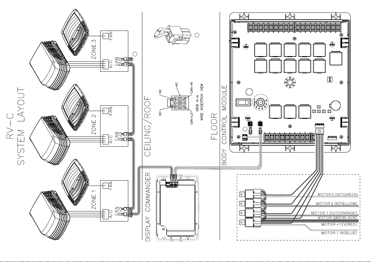
• RV-C SYSTEM LAYOUT
AUX MOTOR CONTROL RELAY KIT (OPTIONIAL)
End of Line terminator resister.
A
A
A

8
NCSP35CM
• SETUP MENU LIST
Tanks, light groups, and motor functions can be added or removed.
Motor functions may include slides, awnings, jacks, or any motor
that may be controlled with a momentary switch.
Refer to the Wiring Diagram and Terminal List when installing new
equipment. The BCM may not include relays for non-OEM
functions. Basic automotive 1505 relays (12VDC Coil, 40/30A
14VDC Contact) can be purchased for installation and repair.
HVAC (Zone1, Zone2, Zone3)
Mode On, Off, Fan, Cool, Heat, Auto
Vent Open, Shut
Vent Fan Off, Low, Medium, High
Schedule Start time, Stop time
Awnings
Awning Light No, Yes
Awning 1 In, Out
Awning 2 In, Out
Settings
Bluetooth Scan
Wi-Fi On, Off, Scan, Add
Date & time Edit
Edit Alarms, Awnings, Lights,
Slides
Passcode Setting
Brightness Up, Down
Calibration Set
Reset Floor plan OEM Floor Plan ,
Default Floor Plan
Information Information notes
Software DC, App, BCM, OTA,
Floor plan
Global Connect Login, Show Passcode,
Clear Account
Administration
App Data, Generator
Hour Meter, Log File,
Tanks
Language English, French
Lights
Light Group 1-2 No, Yes
Awning Light No, Yes
Dimmer Light 1-3 No, Yes
Slides
Slide 1-5 In, Out

9
NCSP35CM
• TRAVEL LOCKOUT (Safety)
iN-Command is equipped with a Travel Lockout feature to ensure
certain system functions are unavailable during transit.
When the Brake Signal (Towable) or Ignition (Motorized) is activated,
the iN-Command will lock down all motorized functions. The Display
Commander (DC) and mobile devices will also display “Travel Lock
Engaged” and the affected buttons will cease to activate.
The lights, water pump, water heater, and sensors will continue to
function.
To turn the Travel Lock off, press "Disengage" on the Display
Commander (DC), inside the RV, once the brake signal has been
removed.
Travel Lock on the Display Commander
Inhaltsverzeichnis
Andere IN-COMMAND Steuerungssystem Handbücher


