
INRODA PUMA Bedienungsanleitung
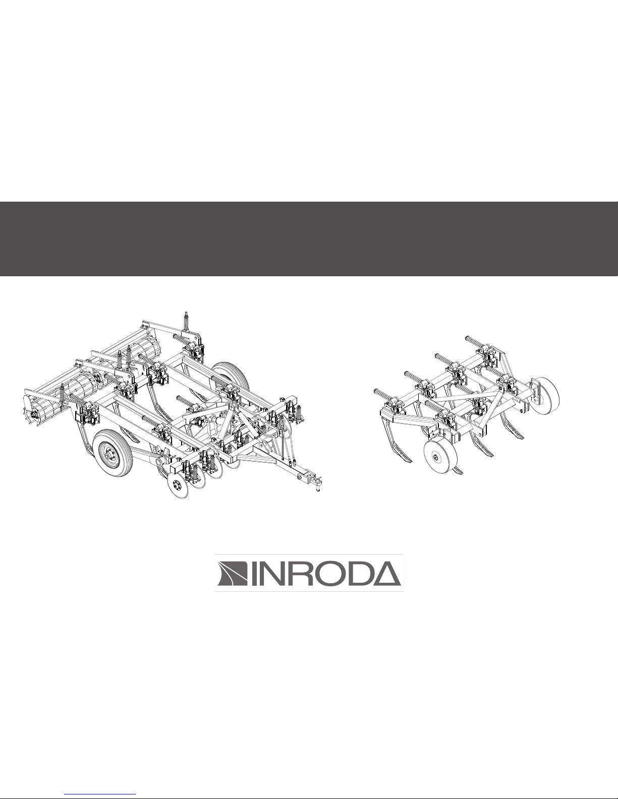
PUMA
SUBSOILER
INSTRUCTIONS MANUAL
PUMA H

01
01 - Introduction
- Warranty certifi cate
02 - Parts:
- Subsoiler Puma
- Subsoiler Puma H
03 - Safety Rules
- Transport over truck
04 - Technical features:
05 - Assembly
- Assembly of ground wheel on the frame
- Wheel Assembly
- Rear roller Assembly
- Coulter Blade assembly
- Hydraulic system assembly
- Drawbar assembly
- Shanks assembly
06 - Hitch:
- Hitching the Subsoiler in the tractor
- Puma H Hitch Procedure
- Puma H Alignment Procedure
- Puma H Leveling Procedure
07 - Adjustment and operations:
- Depth Adjustment for Subsoiler Puma
- Depth Adjustment for Subsoiler Puma H
- Pressure Adjustment in auto-return Device
- Spacing between shanks Puma H
- Coulter Blade adjustment
- Rear Roller Subsoiler Puma
- Operations
08 - Maintenance:
- Lubrication
- Operations maintenance - Problems During the Subsoilers Works
- Operations maintenance - Problems With Hydráulics System
- Lubrication point
- Tyres infl ations
- Subsoiler transport
10 - Clear procedure
11 - Spare parts
12 - Identifi cation
TABLE OF CONTENT
2
3
4
5
6 - 7
8
9
10
10
10
11
11
12
12
13 - 14
15
15
16
16
17
17
18
18
19
19
20
21
21
22
23
24
25
25
26
26
26

02
INTRODUCTION
This manual is an important part of your machine provided by INRODA
Indústria de Roçadeiras Desbravador Avaré Ltda and should remain with
the machine when you sell it.
Reading your operator’s manual will help you and others avoid personal
injury or damage to the machine. Information given in this manual will pro-
vide the operator with the safest and most effective use of the machine.
Knowing how to operate this machine safely and correctly will allow you to
train others who may operate this machine.
The dealer will delivery the equipments and explain about safe working,
maintenance technical support and provide further details about the terms
and conditions of the warranty.
To obtain performance of the warranty, the original purchaser must re-
quest warranty service from a distributor authorized to sell the product to
be serviced .
Following the instructions of this manual and correct maintenance it will
provide a long years of trouble-free from your implement.

03
WARRANTY CERTIFICATE
INRODA Indústria de Roçadeiras Desbravador Avaré Ltda., as manufacturer warrants all parts, (except those referred to below), of the product
described in this manual to be free from defects in materials and workmanship during the period of 6 (six) month from the invoice date to the first
purchaser following the rules bellow :
WARRANTY COVER
The warranty will cover defective parts not subject to normal wear and tear will be repaired or replaced at our option during the warranty period
when the use follow the content of this manual.
To requesting the warranty is necessary show the warranty certificate and invoice with all fields filled in observance of the warranty rules.
WARRANTY VOID CONDITIONS
This warranty does not apply to equipment or parts that have been subjected to improper or unauthorized installation or alteration and modifica-
tion, misuse, negligence, accident, overloading, overspeeding, improper maintenance, repair or storage so as, in our judgment, to adversely affect its
performance and reliability;
Failure to follow recommended operating and maintenance procedures, including maintenance in dealer unauthorized by the manufacturer, also
voids warranty
Maintenance and replacement of parts by not genuine INRODA parts;
Project changes also void the warranty;
Incomplete or incorrect filling of the warranty certificate.
THE WARRANTY DOES NOT COVER:
Damages caused by accidents;
Part damaged by the normal wear unless problems from defects in materials and workmanship.
Fluids and lubricate oil;
Transportation charges on product submitted for repair or replacement under this warranty must be borne by purchaser.
GENERAL CONDITIONS
All equipment and parts replaced under this warranty will become the property of the manufacturer, INRODA;
The warranty of parts replaced are limited of the equipment warranty period above described.
Delay in warranty services does not provide right to reimbursement, indemnification or extending the warranty
04
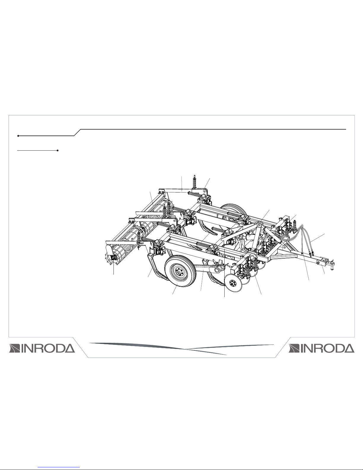
01 - Complete auto-return shank
02 - Complete Wheel
03 - Complete wheel articulation support
04 - Frame
05 - Hydraulic hose support
06 - Hydraulic hoses
07 - Rear roller bearing
08 - Drawbar adjuster
09 - Drawbar hitch device
10 - Rear roller
11 - Complete coulter blade
12 - Attachment rear roller support
13 - Hydraulic cylinder
14 - Rear roller oscillation bar
02 - PARTS
13
14
07
05
12
08
DRAWING 01
09
06
09
04
14
01
02 03 11
10
SUBSOILER PUMA
05
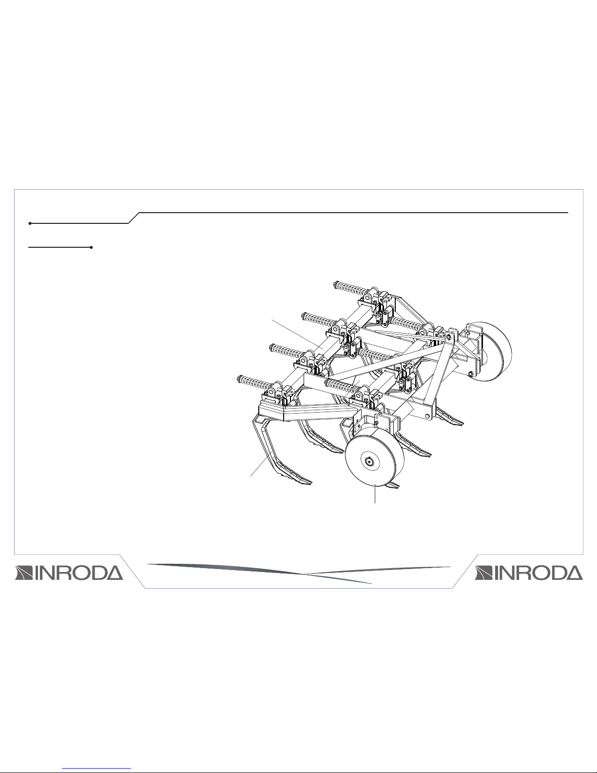
01 - Frame
02 - Complete Shank
03 - Depth control wheels
02 - PARTS
02
01
03
SUBSOILER PUMA H
DRAWING 02

06
03 - SAFETY RULES
THIS IS THE SAFETY ALERT SYMBOL. IT IS USED TO ALERT YOU TO POTENTIAL PERSONAL INJURY HAZARDS.
OBEY ALL SAFETY MESSAGES THAT FOLLOW THIS SYMBOL TO AVOID POSSIBLE INJURY OR DEATH.
1 - Do not keep bystanders, child near of the working area during the operations or over the implement.
2 - Do not turn on the tractor engine in closed place without appropriate ventilation because the gas is bad for health.
3 - Before coupling or uncoupling the hydraulic hoses relief the pressure
4 - Inspect periodically the hydraulic hoses and replace when fi nd any wear or damage, the oil work in high pressure and any damages may result in
serious injuries or death.
5 - Do not any adjustment when tractor is turned on
6 - During the tractor moving by roads pay attention in brake controls and use the safety devices
7 - Before performing any services in the discs gangs wear gloves.
8 - While maneuvering the tractor to hitch the implement be sure that there is enough space and nobody is too close, maneuver always in slow gear
and be ready to brake in case of emergency.
9 - Do not use large clothes because they can get caught on the implement.
10 - Drive the tractor always at safe speeds, especially when working in irregular or inclined lands, keep the tractor always geared.
11 - When working over hilly land try to keep the necessary stability. In case of instability reduce the acceleration, turn the wheels to the inclined side of
the land and never lift the implement.

07
12 - When you start the tractor engine, be correctly placed at the operators seat and be aware of the correct and safe handling of both tractor and imple-
ment. Always place the gearshift crank at the neutral position, turn off the gear of the power command and place the hydraulic commands at the neutral
position.
13 - Do not work with the tractor front’s too light in order to avoiding this problem use the extra-weights
14 - When you leave the tractor set the gear in neutral position and use the parking break. Never leaves the tractor with the hydraulic system raised.
WARNING: The incorrect handing of this implement may result in serious injuries or death. Before using the implement read carefully the ins-
truction manual. Be sure that the person responsible for the operation is instructed about the correct handing and safety and has understood
the instruction manual concerning this machine.

08
TRANSPORT OVER TRUCK
The transport in long distances must be done by a truck or another vehicle able to doing it, following the instructions
below:
- For loading and unload the hoist use proper ramps Do not use hilly places it may result in serious injuries
or death.
- For unloading the hoist use proper anchor points .
- Lock the hoist on the vehicle during the transport.
- Use the proper devices (rope, chain, wire) to attaching the hoist during the transport procedures
- Inspect the hoist after 8km then check ropes and attachment devices every 100km traveled
- Pay attention about the transport height because electrical power lines overhead or in bridges may result
in serious injuries or death..
- Inform about local laws height and width requirements when necessary follow the regulations for lighting
requirements be sure turn signal lights and tail lights are clean and visible.

09
TABLE 01
Model Number
of shank
Working
Width
Spacing between
shanks (mm)
Weight Working depth
(mm)
Tractor
required (CV)
Work
speed
PUMA 3000 H 3 930
310
456
450
45 - 65
4 a 8 km/h
PUMA 5000 H 5 1550 642 60 - 80
PUMA 7000 H 7 2170 860 80 - 105
PUMA 9000 H 9 2790 1039 100 - 130
04 - TECHNICAL FEATURES
TABLE 02
Model Number
of shank
Working
Width
Disc
Diameter
Spacing between
shanks (mm)
Spacing betw
shanks
Working depth
(mm)
Tractor
required (CV)
Work
speed
PUMA 5000 5 1875
18” 375
1552
450
100 - 125
4 a 8 km/h
PUMA 7000 7 2625 2186 140 - 175
PUMA 9000 9 3357 2569 180 - 225
PUMA 11000 11 4125 3098 220 - 275
PUMA 13000 13 4875 3538 260 - 325
Dieses Handbuch passt für folgende Modelle
1
Inhaltsverzeichnis
Andere INRODA Landwirtschaftliche Geräte Handbücher


