
Jeep DIGITAL BRAKE CONTROL Bedienungsanleitung
1
DIGITAL BRAKE CONTROL
GRAND CHEROKEE
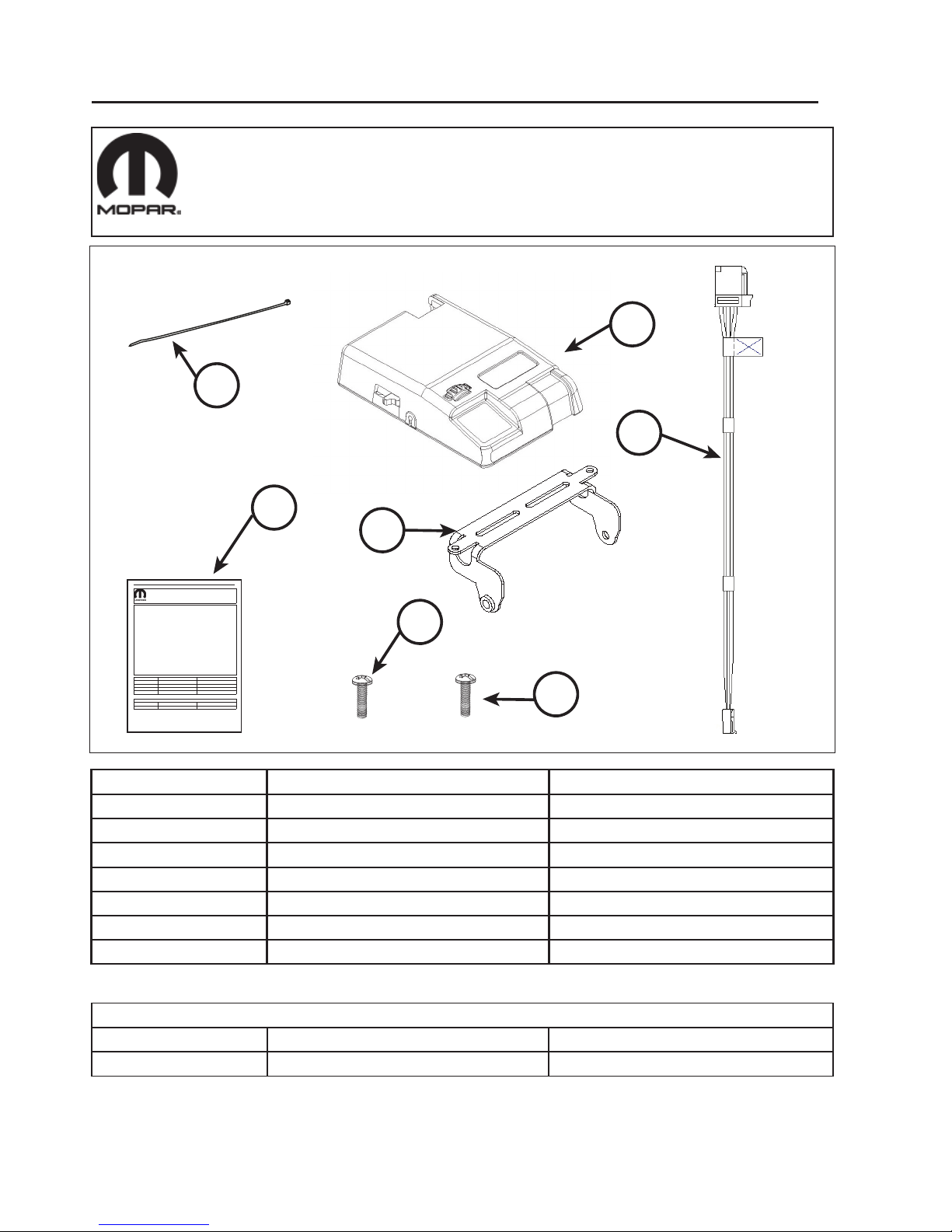
Call Out Description Quantity
1 Brake Control Unit 1
2Brake Control Harness 1
3
4
3.5mm x 13mm Sheet Metal Screw 2
Mar 07, 2012 82213173 Rev. 0
Tools Required
12mm Socket Wrench Power Drill with 1/8” Drill Bit Phillips Screwdriver
6” Cable Ties 3
1
DIGITAL BRAKE CONTROL
GRAND CHEROKEE
Call Out Description Quantity
1 BrakeControlUnitwith Bracket 1
2Brake Control Harness 1
3
4
3.5mm x 13mm Sheet Metal Screw 2
Feb 27, 2012 82213173 Rev. 0
Tools Required
12mm Socket Wrench PowerDrillwith 1/8”Drill Bit Phillips Screwdriver
6” Cable Ties 3
1
2
5
6
7
5
Instruction Sheet 1
Test Light
Brake Control Bracket 1
4mm x 9.5mm Bracket Screw 2
6
7
4
3
2
Installation Procedure:
Feb 27, 2012 82213173 REV. 0
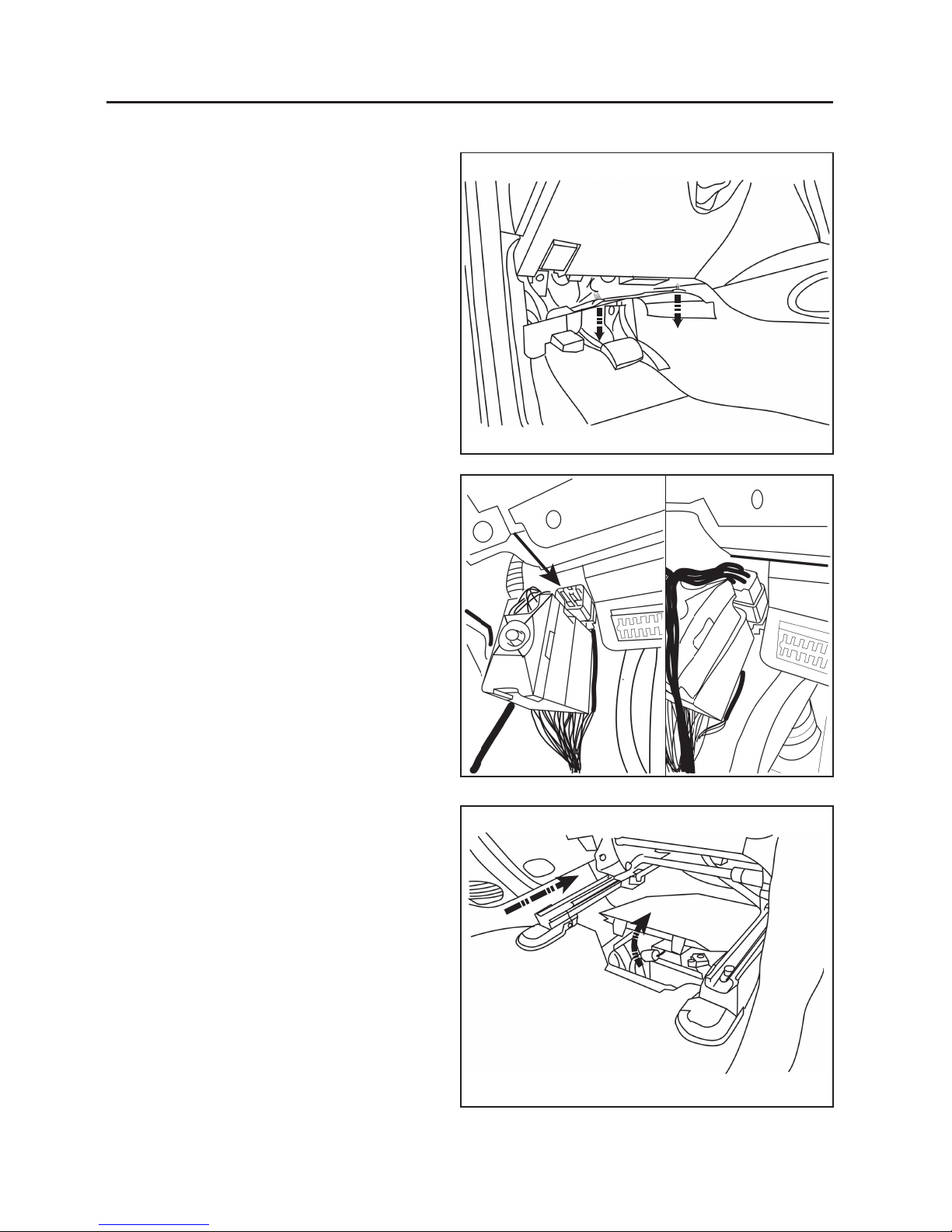
1. Remove the Hush Panel under the steering column.
2. Connect the Brake Control Harness to the vehicle
factory brake control connector. It is located behind
the Diagnostic (ODBII) Connector.
3. Turn On Ignition. Using a test light, probe the
battery terminal of the Brake Control Harness
(Refer to Wiring and Connector Diagram at pg. 10)
to insure power to connector.
4. Also probe the brake input terminal of the Brake
Control Harness (Refer to Wiring and Connector
Diagram at pg. 10) to insure power to connector
when brake pedal is pressed.
5. Be certain that all electrical accessories are turned
off, and write down your radio presets. Turn Off
Ignition.
6. The battery is located underneath the front
passenger seat. If equipped with Power Seats,
move the passenger seat to the most forward and
upright position. If equipped with Manual Seats,
move the passenger seat to the most forward
position.
7. Remove the Battery Cover.

3
Feb 27, 2012 82213173 Rev. 0
8. Using a 12mm socket wrench, loosen the nut (A)
that holds tight the negative battery terminal.
9. Remove the Negative Terminal of the Battery and
set aside carefully.
10. Route the Brake Control Harness behind the
Diagnostic (ODBII) Connector.
11. Secure the harness using 6” cable tie to the
bracket of the courtesy light (A).
12. Secure a second point of the brake control harness
to the dash panel harness (B).
13. Route the Brake Control Harness behind the air
vent, and secure it to the bracket (A) using 6” cable
tie.
A
A
B
A
4
Feb 27, 2012 82213173 REV. 0
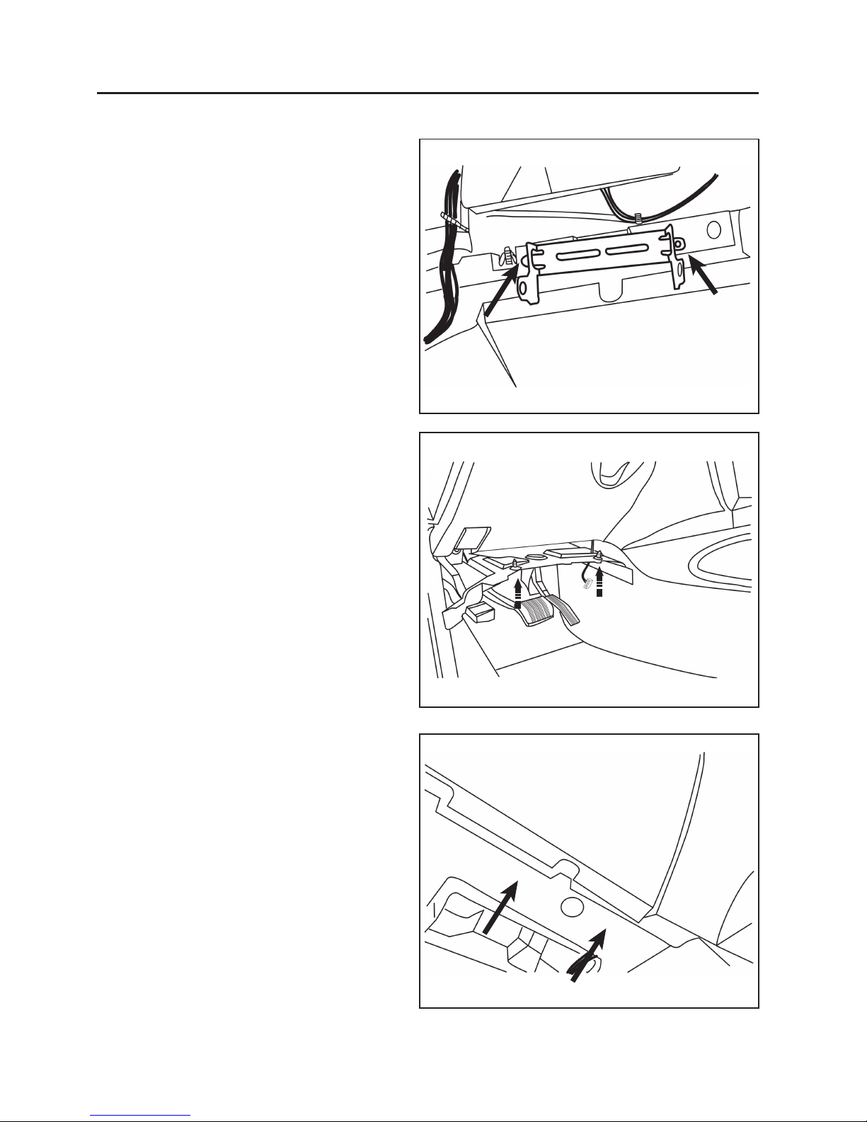
17. Route the Brake Control Harness to the opening of
the air vent in the hush panel.
18. Re-install the hush panel.
19. Drill pilot holes in the hush panel using a Power
drill with a 1/8” drill bit.
14. Position the Bracket of the Brake Control on the
recommended mounting location which is near the
center console in front of the air vent. Align bracket
to optimal mounting area.
15. Ensure the area behind the mounting location is
free of obstructions.
16. Use the mounting holes in the wing tips of the
bracket as a guide, mark mounting holes.

5
Feb 27, 2012 82213173 Rev. 0
20. Install the Brake Control Bracket to the unit.
21. Connect the Brake Control unit to the harness.
22. Mount the Brake Control to the hush panel using
the 3.5mm x 13mm Sheet metal screw on the
wingtip holes.

6
Feb 27, 2012 82213173 REV. 0
25. Install the Battery Cover.
26. Adjust front passenger seat to original position.
27. Turn On ignition, Brake Controller will power up.
23. Reconnect the negative battery terminal.
24. Tighten the 12mm hex nut (A) to secure the
terminal in place
A
7
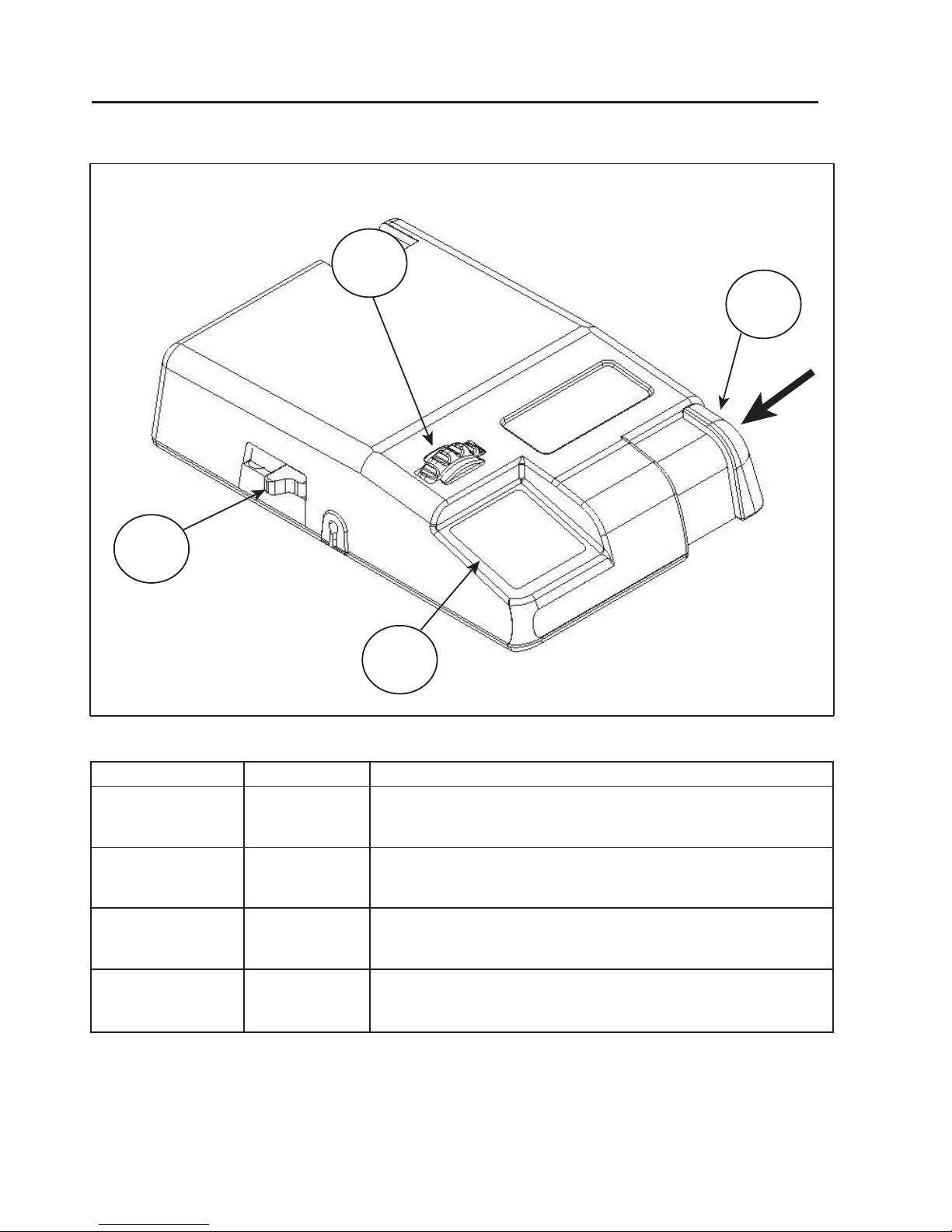
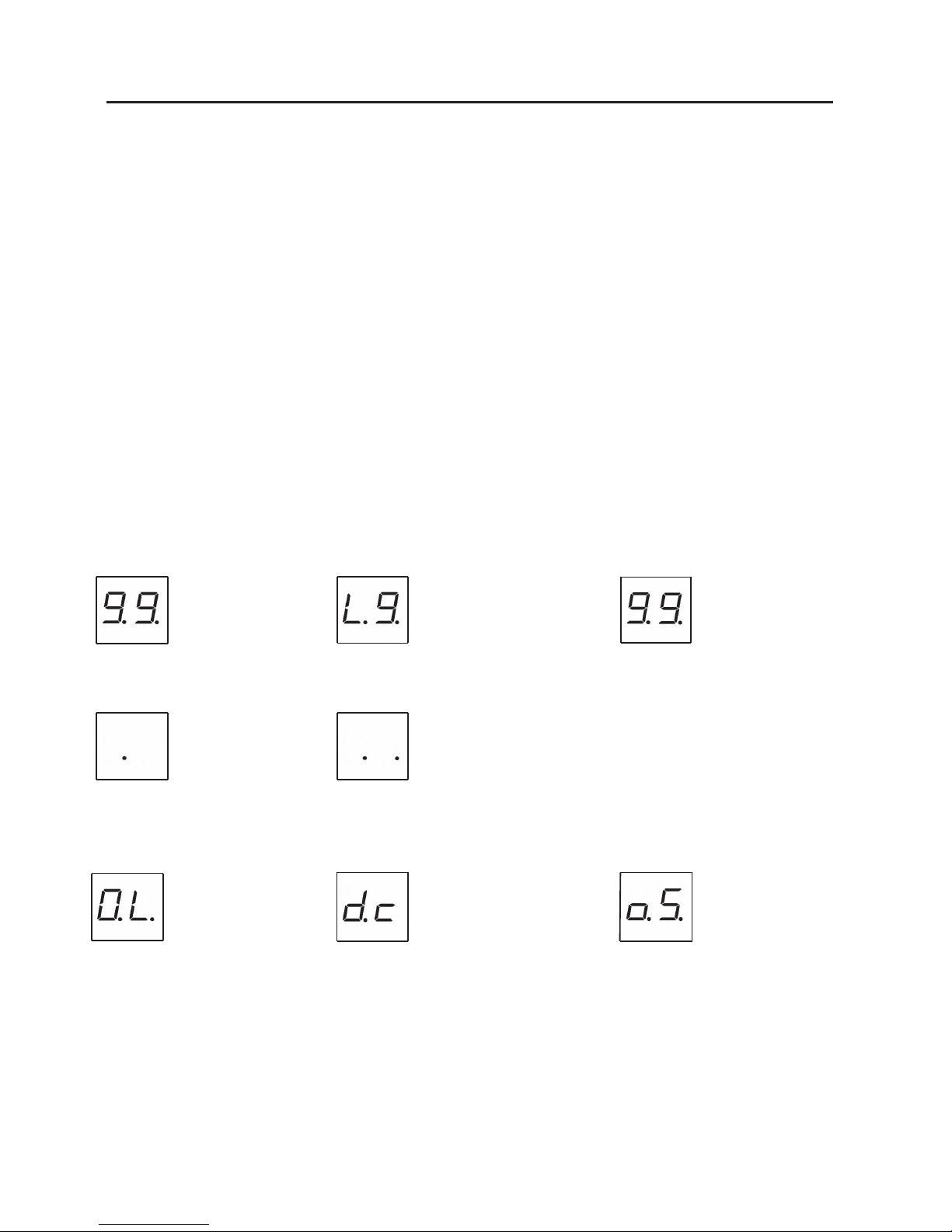
Callout Function Description
Feb 27, 2012 82213173 Rev. 0
1
Establishes the maximum amount of power available to the trailer brakes.
Power ranges from 0.5. to 9.9. with 0.5. as the minimum and 9.9. as the
maximum.
2
3
4
Establishes trailer brakes’ aggressiveness. Ranges from L.1. to L.9. with
L1 being the least aggressive and L.9. being the most aggressive.
Shows the Output setting when the Brake Control is activated. It is used
to setup and monitor the Brake Control and can be used when
troubleshooting.
Activates trailer brakes manually. The more you slide the control, the
higher the braking power will be. It is limited by the Gain setting.
Gain
Sync
Display
Manual Override
Brake Control Operation
1
2
3
4
8
Feb 27, 2012 82213173 REV. 0
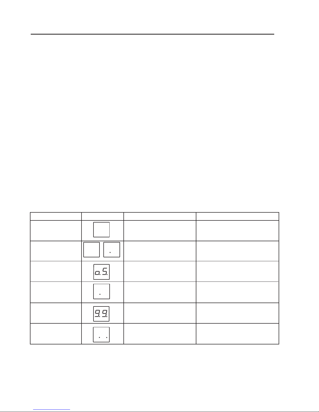
Display Modes:
blinking
Gain Setting
blinking
Sync Setting
Error Codes:
Standby w/o Trailer
Connected
Trailer DisconnectedOutput Overload Brake Lamp Overload
Standby with Trailer
Conected
Brake Power Output
Setup and Adjustment:
Preliminary Adjustment
$GMXVW WKH *DLQ 6HWWLQJ WR E\ WXUQLQJ WKH WKXPEZKHHO OHIW RU ULJKW DV QHHGHG 1RZ PRYH WKH 6\QF 6HWWLQJ
slightly, the display will change to the Sync Setting.
$GMXVWWKH6\QF6HWWLQJWR/E\VOLGLQJWKHFRQWUROIRUZDUGRUEDFNZDUGDVQHHGHG
Test Drive
,QDQRSHQDUHDVXFKDVDODUJHSDUNLQJORWGULYHIRUZDUGDQGDSSO\WUDLOHUEUDNHVXVLQJ0DQXDO2YHUULGH
,IWKHWUDLOHUEUDNHVDUHZHDNLQFUHDVHWKH*DLQ6HWWLQJ,IWKHWUDLOHUEUDNHVMHUNRUORFNWKHZKHHOVGHFUHDVHWKH
Gain Setting.
5HSHDWWKHVWHSDERYHXQWLOILUPEUDNLQJLVIHOWZLWKRXWMHUNLQJRUORFNLQJXSWKHWUDLOHUZKHHOV
2QFHWKH*DLQ6HWWLQJLVVHWGULYHIRUZDUGDQGSUHVVWKHEUDNHSHGDOWKHWRZYHKLFOHDQGWKHWUDLOHUVKRXOGPDNH
a smooth stop.
,IWKHVWRSVHHPVVORZDQGPRUHDJJUHVVLYHEUDNLQJLVGHVLUHGLQFUHDVHWKH6\QF6HWWLQJ,IWKHVWRSVHHPVWRR
aggressive decrease the Sync Setting.
0DNHVHYHUDOVWRSVDWYDULRXVVSHHGVDQGDGMXVWWKH6\QFVHWWLQJXQWLOVWRSVDUHVPRRWKDQGILUP6OLJKWDGMXVWPHQW
RIWKH*DLQ6HWWLQJPD\DOVREHGHVLUDEOH
NOTE: If any problems occur during Setup, refer to the Troubleshooting section.
NOTE: Display will turn off
after 10 minutes in
standby mode.
NOTE: Output Overload will continue to display until the error is rectified (Refer to Troubleshooting Guide
Section) or power is removed from the Brake Control.
Trailer Disconnected will continue to display for 10 seconds then revert to Standby w/o Trailer
Connected if error is not rectified (Refer to Troubleshooting Guide Section).
blinking blinking
9
Condition Display Probable Cause
Feb 27, 2012 82213173 Rev. 0
Setup and Adjustment
Preliminary Adjustment:
$GMXVW WKH *DLQ 6HWWLQJ WR E\ WXUQLQJ WKH WKXPEZKHHO OHIW RU ULJKW DV QHHGHG 1RZ PRYH WKH 6\QF 6HWWLQJ
VOLJKWO\WKHGLVSOD\ZLOOFKDQJHWRWKH6\QF6HWWLQJ
$GMXVWWKH6\QF6HWWLQJWR/E\VOLGLQJWKHFRQWUROIRUZDUGRUEDFNZDUGDVQHHGHG
Test Drive:
,QDQRSHQDUHDVXFKDVDODUJHSDUNLQJORWGULYHIRUZDUGDQGDSSO\WUDLOHUEUDNHVXVLQJ0DQXDO2YHUULGH
,IWKHWUDLOHUEUDNHVDUHZHDNLQFUHDVHWKH*DLQ6HWWLQJ,IWKHWUDLOHUEUDNHVMHUNRUORFNHGWKHZKHHOVGHFUHDVHWKH
*DLQ6HWWLQJ
5HSHDWWKHVWHSDERYHXQWLOILUPEUDNLQJLVIHOWZLWKRXWMHUNLQJRUORFNLQJXSWKHWUDLOHUZKHHOV
2QFHWKH*DLQ6HWWLQJLVVHWGULYHIRUZDUGDQGSUHVVWKHEUDNHSHGDOWKHWRZYHKLFOHDQGWKHWUDLOHUVKRXOGPDNH
DVPRRWKVWRS
,IWKHVWRSVHHPVVORZDQGPRUHDJJUHVVLYHEUDNLQJLVGHVLUHGLQFUHDVHWKH6\QF6HWWLQJ,IWKHVWRSVHHPVWRR
DJJUHVVLYHGHFUHDVHWKH6\QF6HWWLQJ
0DNHVHYHUDOVWRSVDWYDULRXVVSHHGVDQGDGXVWWKH6\QFVHWWLQJXQWLOVWRSVDUHVPRRWKDQGILUP6OLJKWDGMXVWPHQW
RIWKH*DLQ6HWWLQJPD\DOVREHGHVLUDEOH
NOTE: If any problems occur during Setup, refer to the Troubleshooting section.
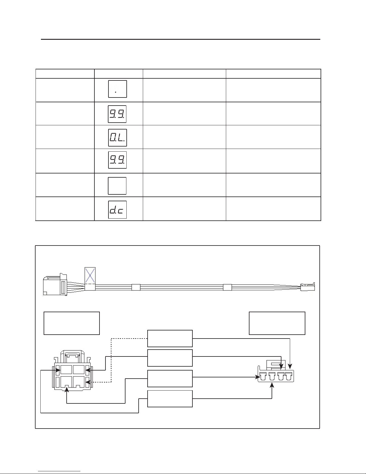
Troubleshooting Guide
NOTE: Test without Trailer connected first.
Possible Solution
'HFLPDO 3RLQW GRHV QRW OLJKW
XS ZKHQ SRZHU LV DSSOLHG
%UDNH 3HGDO RU 0DQXDO
&RQWUROLVXVHG
1R 3RZHU WR %UDNH &RQWURO 1R *URXQG
5HYHUVH%ODFNDQG:KLWHZLUH
&KHFN %DWWHU\ YROWDJH &KHFN %UDNH &RQWURO
+DUQHVV &RQQHFWRU 5HIHU WR :LULQJ DQG
&RQQHFWRU*XLGH
'HFLPDO 3RLQW GRHV QRW OLJKW
ZKHQ %UDNH 3HGDO LV XVHG
'RHV OLJKW XS ZKHQ 0DQXDO
2YHUULGHLVXVHG
R6 VKRZV RQ GLVSOD\ ZKHQ
0DQXDO2YHUULGHLVXVHG
'HFLPDO 3RLQW DOZD\V OLJKWV
XS RU GRHVQ¶W WXUQ RII HYHQ
ZKHQ%UDNH3HGDORU0DQXDO
2YHUULGHLVQRWXVHG
'LVSOD\VKRZV2XWSXW3RZHU
ZKHQ%UDNH3HGDORU0DQXDO
&RQWUROLVXVHG
'LVSOD\ VKRZV 'HFLPDO
3RLQW ZKHQ SRZHU LV DSSOLHG
WRWKH8QLW
1RFRQQHFWWLRQRULQFRUUHFWFRQQHFWLRQDW
VWRSOLJKW VZLWFK %ORZQ IXVH LQ VWRSOLJKW
VZLWFK
,QFRUUHFW FRQQHFWLRQ DW VWRSOLJKW VZLWFK
&RQQHFWHG DW JURXQG VLGH RI VWRSOLJKW
VZLWFK
5HGZLUHFRQQHFWHGWRWKHZURQJVLGHRI
WKH VWRSOLJKW VZLWFK RU WR ZURQJ VZLWFK
&UXLVH&RQWURO0DQXDO29HUULGHZDVQ¶W
UHOHDVHGWRRIISRVLWLRQ
%UDNH &RQWURO +DUQHVV PLVZLUHG %OXH
ZLUH LV FRQQHFWHG WR D GXPP\ ORDG
0LVZLULQJRIZD\WUDLOHUVLGHFRQQHFWRU
%UDNH &RQWURO +DUQHVV PLVZLUHG %OXH
ZLUH LV JURXQGHG 0LVZLULQJ RI ZD\
WUDLOHU VLGH FRQQHFWRU 7UDLOHU %UDNH
JURXQGHG
&KHFN 6WRSOLJKW FLUFXLW &KHFN %UDNH &RQWURO
+DUQHVVUHIHUWR:LULQJDQG&RQQHFWRU*XLGH
&KHFN VWRSOLJKW FLUFXLW &KHFN %UDNH &RQWURO
+DUQHVVUHIHUWR:LULQJDQG&RQQHFWRU*XLGH
&KHFN 0DQXDO 2YHUULGH &RQWURO &KHFN %UDNH
&RQWURO+DUQHVVUHIHUWR:LULQJDQG&RQQHFWRU
*XLGH
&KHFN ZD\ ZLULQJ KDUQHVV &KHFN %UDNH
&RQWURO+DUQHVVUHIHUWR:LULQJDQG&RQQHFWRU
*XLGH
&KHFN ZD\ ZLULQJ KDUQHVV &KHFN %UDNH
&RQWURO+DUQHVVUHIHUWR:LULQJDQG&RQQHFWRU
*XLGH
%UDNH3HGDO 0DQXDO
No Trailer Connected
10
Feb 27, 2012 82213173 REV. 0
Troubleshooting Guide (continued)
Condition Display Probable Cause Possible Solution
Display shows only 1 Decimal
Point when power is applied. No
trailer Brakes when Brake Pedal
or Manual Override is used.
No Connection between Brake Control
and Trailer Brakes - Blue wire circuit.
Confirm connection to Trailer connector. Confirm
connector terminal positions. Check Trailer
Brake wiring.
No trailer brakes when Brake
Pedal or Manual Override is
used
No trailer brakes when Brake
Pedal or Manual Override is
used.
Weak or No Trailer Brakes.
Trailer Brakes ON all the time.
No Trailer Brakes when Brake
Pedal or Manual Override is
used.
Miswired trailer connector.
Short circuit in Trailer Brakes.
Miswired trailer connector
Miswired trailer connector
Trailer side connector got disconnected.
Confirm Trailer side connector terminal
positions.
Troubleshoot trailer brake circuit per brake
manufacturer’s instructions.
Check and correct trailer side connector wire
positions
Check and correct trailer side connector wire
positions.
Stop and Check Trailer Connector
Trailer Connected
Wiring and Connector Diagram
To Vehicle Factory
Plug To Brake Control
Unit
BLACK WIRE
(+12V BATTERY)
BLACK WIRE
(+12V BATTERY)
BLACK WIRE
(+12V BATTERY)
BLACK WIRE
(+12V BATTERY)
Inhaltsverzeichnis
Sprachen:
Andere Jeep Automobilteil Handbücher


