
Krill ULTIMATE 300KS Mk2 39% Bedienungsanleitung

1
ULTIMATE 300KS Mk2 39%
Assembly Guide
Dear customer,
thank you for choosing ULTIMATE 300KS Mk2 39% model airplane.
Original kit Ultimate 300 KS was developed by our team for patern and 3D flying too. Kit has had
great flying characteristics, but not sufficient for top competitive flying. We decided to improve it‘s
flying characteristic and in cooperation with great Italian pilot Sacha Checconi was created new
version Mk2 built on strong base of current kit and test it with our pilot Marek Plichta.
And what are the differencies?
At first, we put close together top to bottom wing and engine axis is now right in the middle of the
wings. At second we enlarged ailerons on all wings at depth and lenght too, overall area is now
bigger to original more than 60% ! Kit gets uncredible flying agility also during harier tricks. We
also decreased overall weight at the same time reinforced wings (new wing spar) for higher drain
during aggresive 3D flying . New is fixing of cabane inside the fuselage, new interplane struts , new
holder of tanks and already instaled rudder servo tray. Holder of main landing gear is also
redesigned, Gabriel horns are used on all control surfaces, as well as new builder friendly servo
fixing on the wings.
The ULTIMATE 300KS Mk2 kit is a full composite biplane kit, with main top wing from one piece
and bottom wings a horizontal stabilizator spar made from carbon fibre tubes. Both wings and
horizontal stabilizator can be easily removed for transporting. Tail control surfaces has central
hinges.
Content page
1. Technical data............................................................................................................................2
2. General informations.................................................................................................................2
3. Setting and setup.......................................................................................................................3
4. Recommended servos ...............................................................................................................4
5.Assembly...................................................................................................................................4
5.1 Empenage....................................................................................................................4
5.1.1 Rudder..........................................................................................................4
5.1.2 Horizontal stabilizator..................................................................................5
5.1.3 Elevator ........................................................................................................6
5.2 Wing assembly ............................................................................................................7
5.2.1 Servo install..................................................................................................7
5.2.2 Linkage.........................................................................................................8
5.3 Fuselage...................................................................................................................... 9
5.3.1 Rudder drive linkage .................................................................................. 9
5.3.2 Engine installation .....................................................................................10
5.3.3 Fuel & Smoke Tank installation................................................................11
5.3.4 Equipment installation................................................................................12
5.4 Landing gear..............................................................................................................12
5.4.1 Main landing gear.......................................................................................12
2
5.4.2 Tail wheel ...................................................................................................14
5.5 Cowling.....................................................................................................................15
1. Technical data:
Wingspan
2
330
mm
Length
2
55
0 mm
Weight (RTF)
15
kg
Wing area
1
60
dm2
Wing loading
93
,7
5
g/dm2
Engine (Gas)
100
-
130
ccm
Minimum RC channels
6
Notice: ThisAssembly guide only shows how the model could be assembled. According to
model specification we expect, that this airplane is assembled by experienced user, which will
use his habbits and skills to finish it.
As an accesories (levers, rods, fuel caps and fills, etc.) we recommend Secraft. Sets which you can
order as order number:
2051000-50 for Hitec servos
2051000-51 for Futaba servos
2051000-52 for JR servos.
Here is list of Secraft parts for linkage:
Servo arm D40 mm (for aileron and elevator)
6
Double servo arm Offset D90mm (for rudder)
1
Double
servo arm D64mm (for rudder)
1
SEC Ball links M3 (10)
1
SEC M3 Push rod of ALU 60 mm (for elevator)
1
SEC M3 Push rod of ALU 70 mm (for aileron
and rudder)
3
For rudder is higly recommended SECRAFT rudder pull-pull set BASE No.: 2050130-01
or SPORT set No.: 2010130-02
2. General informations
all nuts should be secured against looseninig (use Loctite 243)
make sure, that all control surfaces can move freely
all holes drilled in airplane surfaces, that is not factory made, must be reinforced (with
rowing, plywood, etc.)

3
protect your airplane against hot (it can cause material degradation). Please notice that dark
surface can heat up to 90°C/194°F in sunny summer days!!
use protecting coats (you can order them with kit or separetely via [email protected]
email)
please take into count that there are a lot of carbon fiber in your model, make sure that your
receiver has full signal
KRILL model takes no responsibility for damages incurred during the assemblying, flying, using or
transporting this model airplane.
3. Setting and set up
Setting – incidence and CG
Basic setup:
Ailerons deflection 20degrees, expo 40 – 50%
Elevator deflection 30degrees, expo 50 – 60%
Rudder deflection 30degrees, expo 50 – 60%
Idle 1 for 3D:
Ailerons deflection 30degrees, expo 60 – 70%
Elevator deflection 40degrees, expo 60 – 70%
Rudder deflection 40degrees, expo 60 – 70%
Idle 2 for 3D:
Ailerons deflection 45degreess – full, expo 70 – 80%
Elevator deflection 60degrees – full, expo 70 – 80%
Rudder deflection 50degrees – full, expo 70 – 80%
4
4. Recommended servos:
You can use any strong and fast servos in standard size.
Recommended torque: min 25 kg/cm
Recommended speed: 0,08 – 0,11 s5.
5. Assembly
5.1 Empenage
5.1.1 Rudder
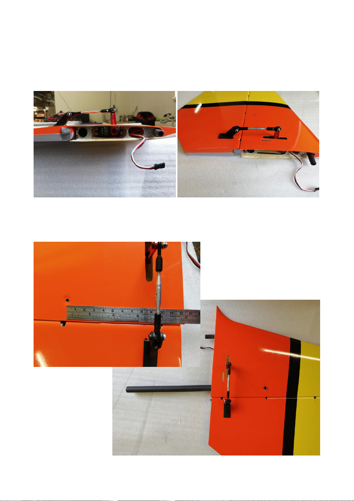
Firstly you must shorten the pegs of Gabriel horns 6/27 to the lenght 13 mm.
Than glue in horns into the prepared holes using an epoxy resin.
5
5.1.2 Horizontal stabilizator
Two operation for horizontal stabilizators is needed. First is to place the servo and drill the hole for
servo lever. Make sure that lever has enought space for full movement. Otherwise the lever can
damage stabilizator surface!
Second operation is to secure horizontal stabilizator against motion. This can be done two ways.
First is to drill hole, which goes throught surface and carbon fiber tube (stabilizator spar). And
place a pin (or screw) into this hole. This operation has to be done on both halfs!

6
5.1.3 Elevator
Use Gabriel horns 6/20 size from accessories. Glue it to predrilled holes on both elevators.
For linkage use Secraft turnbuckle ALU pushrod 60 mm long, from one side is mounted Secraft ball
link M3, from second original Gabriel ball link, overall lenght of the link is 80 mm. 40 mm ALU
Secraft V2 servo arms is used there.

7
5.2 Wing
5.2.1 Servo install
First, we will schedule the cables of individual servos of the ailerons to the receiver / central unit.
The cable of the servo of the left upper aileron is led through the shaft into the hole in the lower
part of the cover in the space of the inter-wing strut (for easier routing of the cable, a string is
prepared here).
The cable then continues through the interwing strut to the left lower wing, where it continues from
the root of the lower wing to the fuselage of the model. The same goes for the right side. To
maintain the demountability of the wings and the inter-wing struts, the cable between the wing and
the inter-wing strut should be interrupted by connectors.
It is advisable to use PowerBox ONE4ONE cable sets. 2 cables (upper left and lower left aileron
servos) protrude from the root of the lower wing. Here it is suitable to use the PowerBox
ONE4TWO cable set between the fuselage and the wing.
The cable outlet terminated with a connector (ONE4TWO) from the root rib of the lower wing has
proven to be fastened by means of a mounting frame.

8
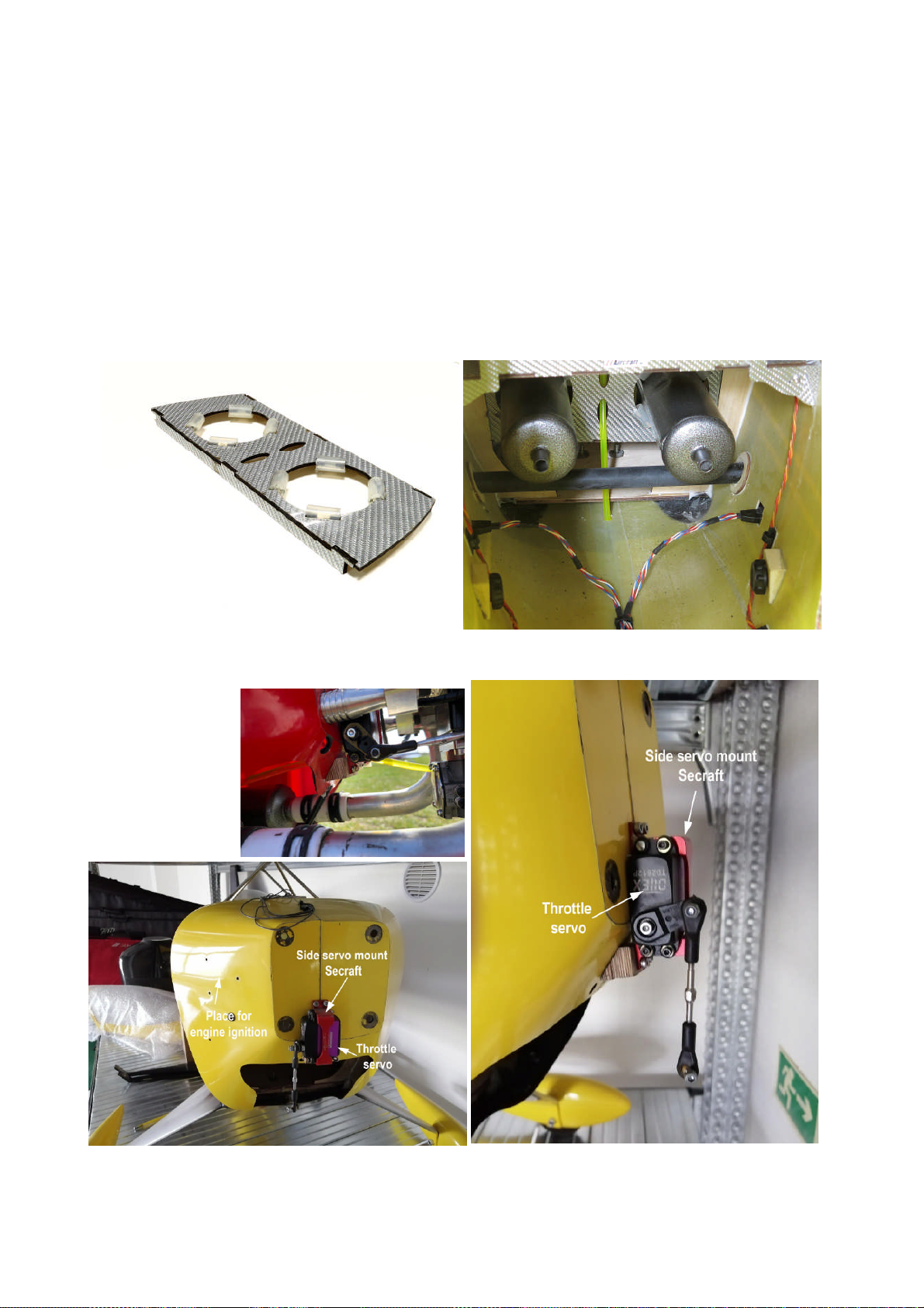
Installation of servos in the upper as well as in the lower wings is now very simple, thanks to the
new servo holder with an integrated servo shaft cover. The servo is first mounted in the individual
holders / covers, it is best fitted with a 40 mm long Secraft arm. Center the lever in the middle
position. After passing the cables, the whole cover with the servo is then inserted into the shaft and
fastened with the enclosed 4 screws.
5.2.2 Linkage
Glue the supplied Gabriel horns size 6/20 into the prepared pair of holes. First, shorten the pins on
the horn to 12 and 8 mm according to the picture. Glue the horns into the holes with epoxy resin.
Servo arm is connected with the Gabriel horn using a linkage made of a 70 mm long pushrod,
terminated on one side by an original ball link from Gabriel horn and on the other side by a Secraft
ball link.

9
5.3 Fuselage
The installation of the internal equipment of the fuselage of the model is very individual, it depends
on the habits of the builder, but especially on the equipment used, consider the following lines as
informative, what the internal installation of the fuselage may look like.
The model comes standard with a number of accessories that you can use:
- Exhaust holder
- Tank holder
- Battery holders
5.3.1 Rudder drive linkage
We recommend to use 2 standard servos mounted in the already glued deck to drive the rudder. The
rear (end servo) is equipped Secraft double sided offset arm 90 mm, the front servo is equipped with
a Secraft double side straightde arm 64 mm, the arms are interconnected by linkages formed by ball
links Secraft and pushrods 70 mm. Than the drive itself is solved by a pull-pull drive using a
Secraft Rudder pull-pull set BASE or SPORT.
10
5.3.2 Engine installation
The MVVS116NP engine was used for the model prototype shown. You can use any engine (2-
cylinder boxer) size about 100-120 cc. The engine is mounted offset to the right 2.5 degrees,
horizontally at zero. It will probably always be necessary to mount the engine using spacers of
suitable length so that prop hub plane is about 2-3 mm in front of the engine cover plane and
respects the engine misalignment, ie the engine axis at the prop hub level intersects the vertical axis
of the model fuselage.
Silencers of any type can be placed on the engine, as often of the cup type, which are standardly
supplied with some engines (DLE, etc.), but better, due to the noise limits, by the silencer with
headers.
You can use the supplied 60 mm diameter muffler exhaust holder for this exhaust system.
The servo to control the carburetor should be placed under the engine using the Secraft side servo
mount - see the picture.
Place the engine ignition on the side sloping wall of the firewall.
Inhaltsverzeichnis
Andere Krill Spielzeug Handbücher


