
Licht MFC-200/N Bedienungsanleitung

Level Monitor
model MFC-200/N
Technical Manual
Licht

Licht http://www.licht-labs.com
Rev. B0 (20–05–08) MFC-200/N Technical Manual 2
1 Introduction
The MFC-200/N is a precise, highly reliable and versatile microcontrolled system designed
to read, display and retransmit multiple channels containing level information. The MFC-
200/N can be supplied in configurations with up to 6 input channels and 12 independently
configurable relays. Each relay may be associated with any input, and has a configurable
setpoint, hysteresis and activation delay.
The MFC-200/N features 6 compensated resistive sensor inputs, 1 isolated RS-485 port,
12 configurable relays, 6 isolated configurable current loop outputs and up to 2 failure
indication relays.
The MFC-200/N shares its form factor with other Licht controllers for transformers, such
as the MFC-200/R voltage regulator and the MFC-200/P parallelism controller. Like all
Licht controllers, the MFC-200/N was designed for use under severe conditions, including
high temperatures, electromagnetic interference, surges, impulses and overvoltage. All
signals that enter and exit the controller are pairwise galvanically isolated. This prevents
potentially damaging noise and transients from being transferred to the equipment’s in-
terior or retransmitted to other devices connected to it.
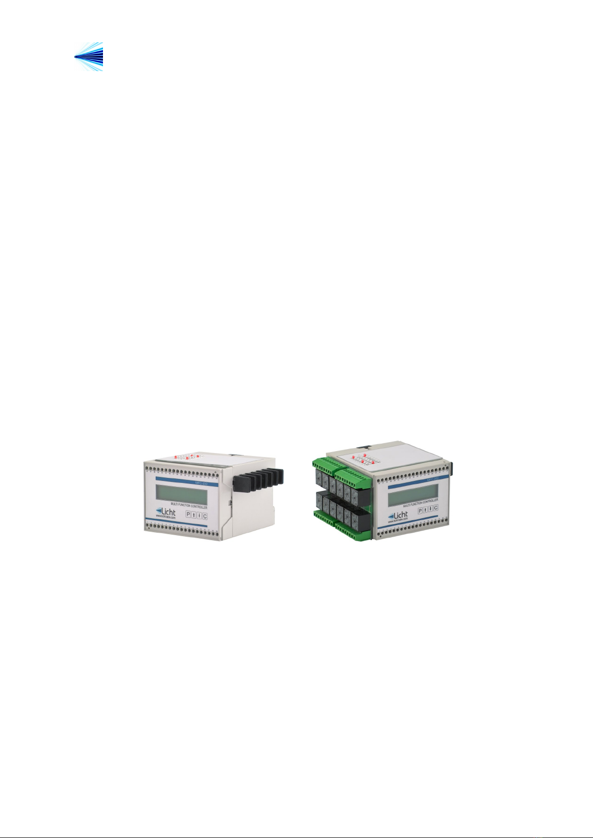
Figure 1.1 MFC-200/N Controller
Licht http://www.licht-labs.com
Rev. B0 (20–05–08) MFC-200/N Technical Manual 3
2 Front panel indication
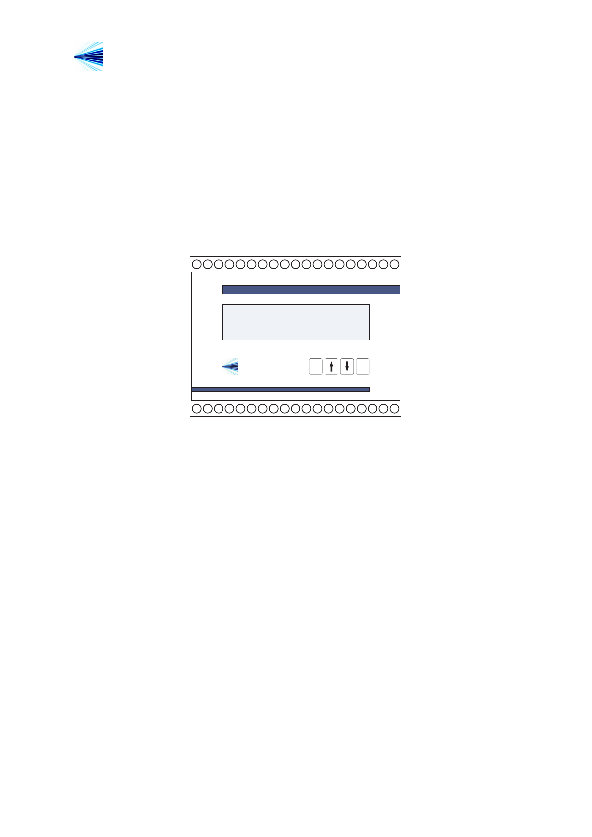
During operation, the MFC-200/N alternates each channel’s level indication, presented
as a percentage value. This indication depends on the calibration performed by the user
before commisioning.
A timer automatically changes the channel on display. The user may manually alter the
currently displayed channel (skipping the alternation timer) by pressing the ↑or ↓keys.
CP
Licht
www.licht-labs.com
MULTI-FUNCTION CONTROLLER
MFC-200/N/2
12345 6 7 8 9 10 11 12 13 14 15 16 17 18 19
38 37 36 35 34 33 32 31 30 29
28
27 26 25 24 23 22 21 20
Level 1: 78.5 %
Level 2: 62.3 %
Figure 2.1 Front Panel

Licht http://www.licht-labs.com
Rev. B0 (20–05–08) MFC-200/N Technical Manual 4
3 Configuration
Parameterization
The MFC-200/N features 4 keys to access its functions. The procedure to configure any
parameter is as follows:
1. Press the Pkey to enter the parameters menu.
2. Using the ↑and ↓keys, choose the desired parameter.
3. Press Pto confirm the parameter’s selection.
4. Choose the desired value with the ↑and ↓keys.
5. Confirm by pressing P.
The configuration sequence can be cancelled at any time by pressing C.
The configuration menu is protected by a 4 letter password, designed to discourage unau-
thorized reconfiguration attempts. The default password is AAAA. If the password is ever
lost, it may be reset along with all other parameters by powering the device while pressing
the Ckey. This procedure does not reset the sensor calibration.
Calibration
Each MFC-200/N is pre-calibrated to the potentiometric sensors expected to be used by
each client. Recalibration can be easily performed by following these steps:
1. Power up the device while pressing the ↑or ↓key.
2. The indication Min Channel 1 will appear on the display, along with a raw sensor
readout between 0 and 65535. Manually move the level sensor to its minimum
position (corresponding to the 0% excursion). The readout will reflect this position.
3. Press Pto store this minimum value.
4. The indication Max Channel 1 will appear on the display, along with a raw sensor
readout between 0 and 65535. Manually move the level sensor to its maximum
position (corresponding to the 100% excursion). The readout will reflect this po-
sition.
5. Press Pto store this maximum value.
6. Continue this procedure to calibrate the remaining channels.

Licht http://www.licht-labs.com
Rev. B0 (20–05–08) MFC-200/N Technical Manual 5
4 Programmable parameters
The MFC-200/N was developed to provide the user with the greatest possible flexiblity,
such that all supervision and configuration can be executed on-site or remotely through
the existing communication channels.
We define all user-configurable parameters as follows:
Parameter:Set Point[1-12]
Options: 0 to 100%, in 1% increments.
Description: Set point for relays 1-12.
Parameter:Hysteresis[1-12]
Options: 1 to 50%, in 1% increments.
Description: Hysteresis for the activation/deactivation of relays 1-12. A hysteresis value
of at least 1% is required to prevent relays from switching on and off intermittently
whenever the indication remains over an activation threshold.
Parameter:Delay[1-12]
Options: 0.1 to 25.5 minutes, in 0.1 minute increments.
Description: Activation delay for relays 1-12.
Parameter:Forced Activation[1-12]
Options: Normal, Activated.
Description: Selects if a relay responds to level variations (Normal) or if it is constantly
activated (Activated).
Parameter:Activation Logic[1-12]
Options: Normal, Inverted.
Description: Defines whether a relay’s activation logic is Normal (relay closes when its
set point is exceeded) or Inverted (relay opens when its set point is exceeded).
Parameter:Associated Channel[1-12]
Options: 1 to 6.
Description: Input associated with a particular relay.

Licht http://www.licht-labs.com
Rev. B0 (20–05–08) MFC-200/N Technical Manual 6
4.1 Current outputs
Parameter:Output Scale
Options: 0-1, 0-5, 0-10, 0-20, 4-20 mA
Description: Refers to the various configurable current loop scales.
4.2 MODBUS protocol
Parameter:Baud Rate
Options: 9600, 19200, 38400, 57600, 115200 bps.
Description: baud rate for the RS-485 link.
Parameter:Format
Options: 8N1, 8E1, 8O1, 8N2.
Description: symbol transmission format, where:
◦8N1: 8 data bits, no parity, 1 stop bit.
◦8E1: 8 data bits, even parity, 1 stop bit.
◦8O1: 8 data bits, odd parity, 1 stop bit.
◦8N2: 8 data bits, no parity, 2 stop bits.
Parameter:Address
Options: 1 to 247.
Description: MODBUS address for the MFC-200/N.

Licht http://www.licht-labs.com
Rev. B0 (20–05–08) MFC-200/N Technical Manual 7
A Specifications
Power Supply Isolated, 80-260 Vac/Vdc.
Power Consumption 8W
Operating Temperature -20 to 70 ◦C
Enclosure Rating IP20
Mounting Options 35 mm DIN Rail
Dimensions 100 x 75 x 110 mm
Weight 1.0 kg
DC Inputs Types: potentiometric, current loop, volt-
age
Error/Non-linearity: 0.1%
Current Outputs Scales: 0-1, 0-5, 0-10, 0-20, 4-20 mA
Error/Non-linearity: 0.1%
Galvanic Isolation
(60 Hz, 1 min.)
Outputs 1.5 kV
Communication 1.5 kV
Communication RS-485 - MODBUS RTU or DNP3
9600, 19200, 38400, 57600, 115200 bps
8N1, 8E1, 8O1, 8N2
Displays 2 lines with 16 characters each (5 mm).
LCD with backlight.
Relays 10 A@ 250 Vac, 0.5 A@ 125 Vdc
Galvanic Isolation: 1.5 kV, 60 Hz, 1 min.

Licht http://www.licht-labs.com
Rev. B0 (20–05–08) MFC-200/N Technical Manual 8
B Housing

Licht http://www.licht-labs.com
Rev. B0 (20–05–08) MFC-200/N Technical Manual 9
C Connection diagrams
Inhaltsverzeichnis


