Linmore LED ACE LED AA1 Bedienungsanleitung

Linmore LED Labs, Inc. | 2360 S Orange Ave, Fresno CA 93725 | 559-485-6010 | linmoreled.com | [email protected]
INSTALLATION INSTRUCTIONS
Fixtures must be installed and wired in
accordance with the National Electrical Code
(NEC) and all applicable local codes by a person
familiar with the construction and operation of
the product and hazards involved.
Proper grounding is required for safety.
Check that voltage is compatible with xture
driver, use approved connectors for all electrical
connections.
Be cautious of any sharp edges. Wear proper PPE
(personal protected equipment) while handling.
Fixture not suitable for use in corrosive
environments, and with thermal insulation.
Risk of re or electric shock. Make sure power is off at
the circuit breaker before installing or maintaining the
product.
To prevent wiring damage or abrasion, do not expose
wiring to edges of sheet metal or other sharp objects.
Installation guide requires knowledge of luminaire
electrical systems. If not qualied, do not attempt
installation. Contact a qualied electrician.
Never perform maintenance or cleaning while xture is
energized. Disconnect power and allow xture to cool
off before maintaining.
Review the diagrams before beginning and make sure the
xture is grounded properly.
For lighting controls, use driver wiring diagram.
Maintenance must be done by qualied electricians.
Use a clean, dry cloth to clean the xture.
WARNING
Risk of Fire or Electric Shock
MAINTENANCE CAUTION
READ CAREFULLY BEFORE INSTALLING THE FIXTURE.
PLEASE KEEP THIS MANUAL FOR FUTURE USE.
Page 1 of 12
Rev. 2024.02.01
ACE LED AREA LIGHT (AA1)
For any questions regarding wiring, installation, or
use of this xture, please call 559-485-6010 or email

Linmore LED Labs, Inc. | 2360 S Orange Ave, Fresno CA 93725 | 559-485-6010 | linmoreled.com | [email protected]
Ace LED Area Light (AA1) Installation Instructions
Part No. Watts
(ADJ) Size CCT
(ADJ) CRI Input
Voltage Dimmable Warranty
AA10S-A2-ADJ-MD-ADJ-80-T3-LV-BRN-BB-Z10R-CW-SRG-10V 75
100
120
150
MD
3000K
4000K
5000K
≥80
AC
120-277V
0-10V 5 Years
AA10S-A2-ADJ-MD-ADJ-80-T3-HV-BRN-BB-Z10R-CW-SRG-10V AC
220-480V
AA10S-A2-ADJ-LG-ADJ-80-T3-LV-BRN-BB-Z10R-CW-SRG-10V 175
200
240
300
LG
AC
120-277V
AA10S-A2-ADJ-LG-ADJ-80-T3-HV-BRN-BB-Z10R-CW-SRG-10V AC
220-480V
TECHNICAL SPECS
Page 2 of 12
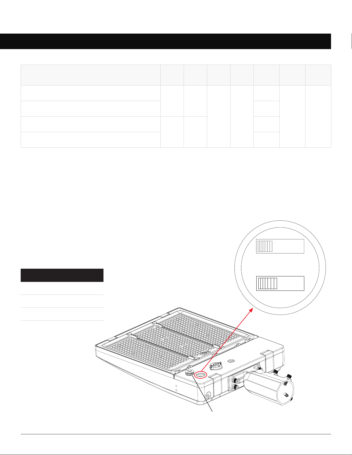
Adjusting Wattage and Color Temperature
1. Make sure the xture is off.
2. Unscrew the 3/4” plug.
3. Adjust the corresponding dip switches to desired wattage and CCT.
4. Install and tighten the 3/4” plug.
Fixtures ship from the factory with the highest wattage and 5000K CCT,
to change these settings:
3/4” Plug
CCT MULTIPLIER
3000K 0.933
4000K 1.000
5000K 0.967
Lumen Multipliers
5K 4K 3K
xxxW xxxW xxxW xxxW

Linmore LED Labs, Inc. | 2360 S Orange Ave, Fresno CA 93725 | 559-485-6010 | linmoreled.com | [email protected]
Ace LED Area Light (AA1) Installation Instructions
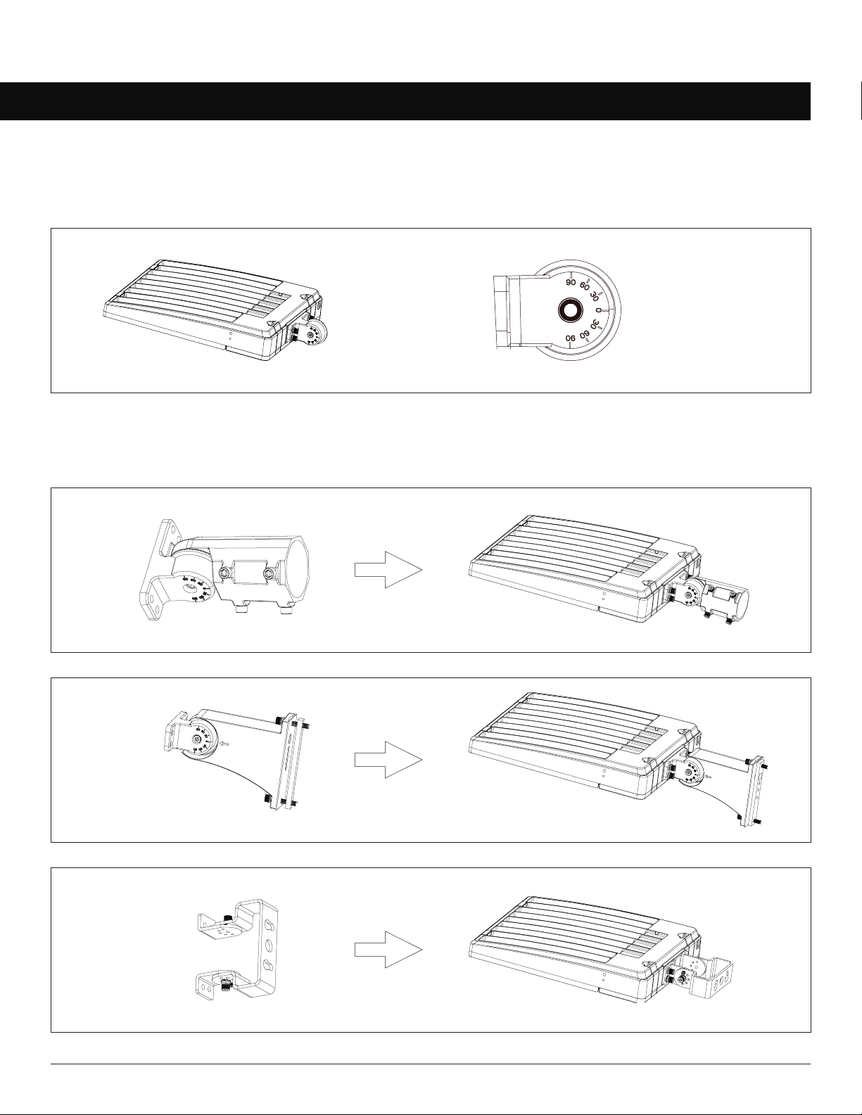
MOUNTING
Mounting Brackets
Slip Fitter
AA1-SF
Straight Arm
Trunion (Yoke)
Mounting brackets are sold separately and are eld installed.
Bracket Base
The xture ships with the Bracket Base attached to it. Mounting brackets can be attached to the base with just one screw.
AA1-SA
AA1-TM

Linmore LED Labs, Inc. | 2360 S Orange Ave, Fresno CA 93725 | 559-485-6010 | linmoreled.com | [email protected]
Ace LED Area Light (AA1) Installation Instructions
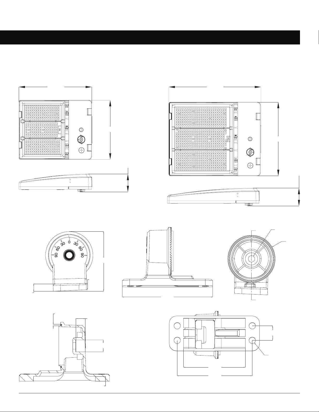
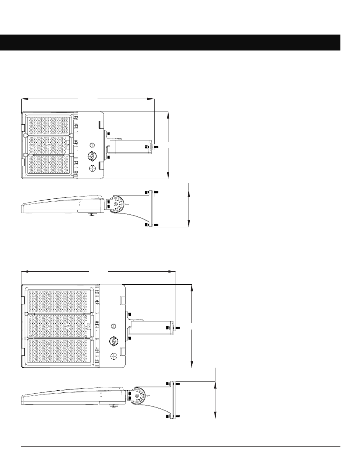
Fixture Only
MD LG
13.88”
11.31”
3.42”
17.55”
14.07”
3.42”
DIMENSIONS
Page 4 of 12
Bracket Base
0.39”
0.35”
3.23”
4.88”
Ø 0.35”
Ø 2.56”
A
0.08” 0.51”
0.64”
0.26”
3.35”
4.05”
0.79”
Ø 4-0.35”

Linmore LED Labs, Inc. | 2360 S Orange Ave, Fresno CA 93725 | 559-485-6010 | linmoreled.com | [email protected]
Ace LED Area Light (AA1) Installation Instructions
DIMENSIONS
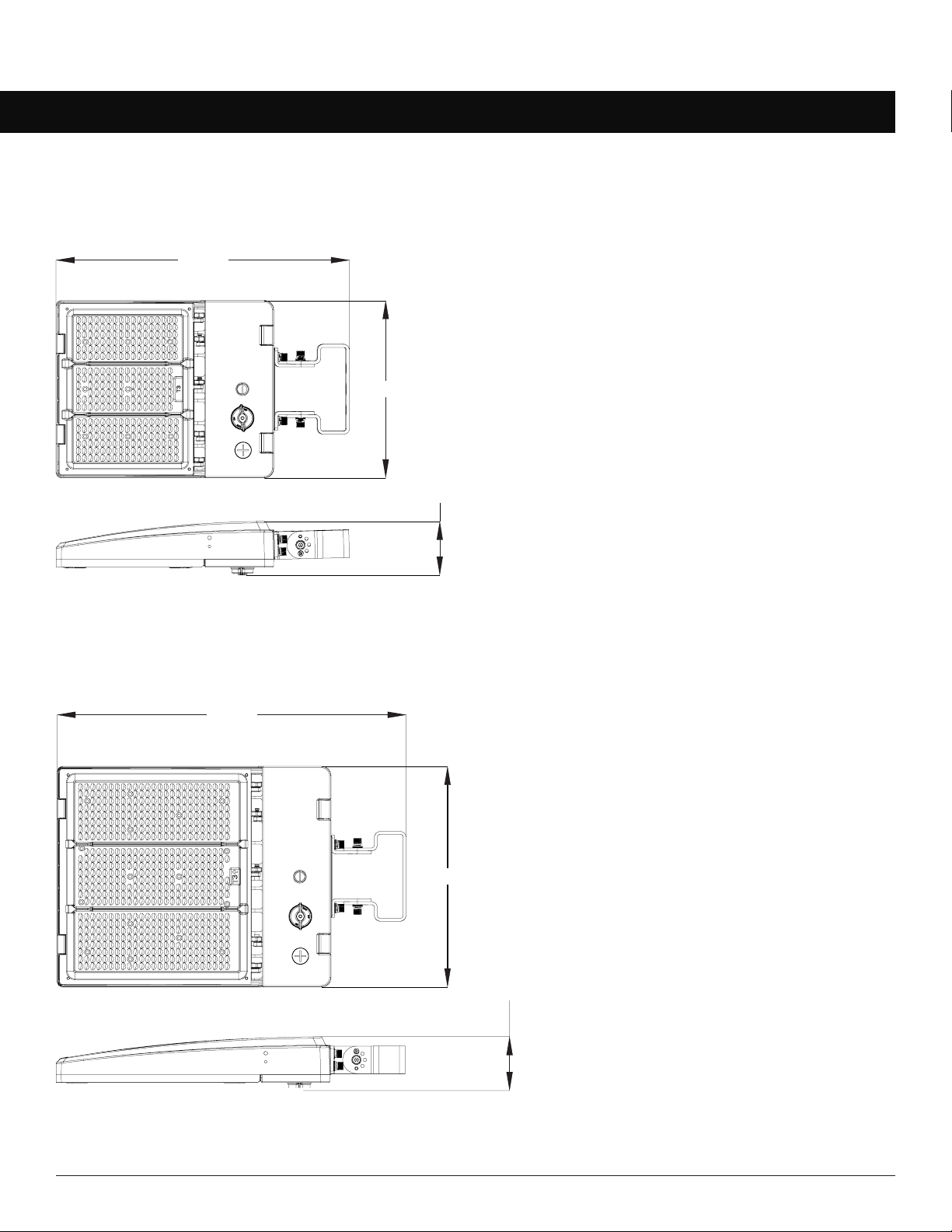
Fixture with Slip Fitter
MD
LG
20.74”
11.31”11.31”
3.58”
24.33”
14.07”
3.58”

Linmore LED Labs, Inc. | 2360 S Orange Ave, Fresno CA 93725 | 559-485-6010 | linmoreled.com | [email protected]
Ace LED Area Light (AA1) Installation Instructions
DIMENSIONS
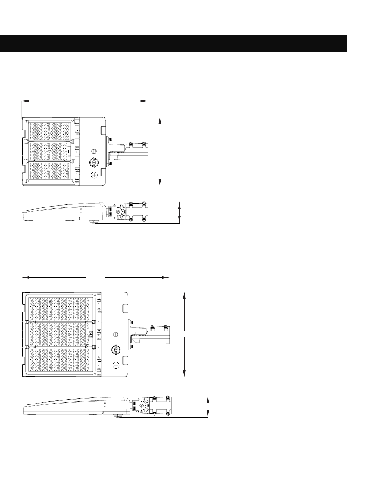
Fixture with Straight Arm
MD
LG
22.30”
11.31”
6.24”
25.89”
14.07”
6.24”

Linmore LED Labs, Inc. | 2360 S Orange Ave, Fresno CA 93725 | 559-485-6010 | linmoreled.com | [email protected]
Ace LED Area Light (AA1) Installation Instructions
DIMENSIONS
Fixture with Trunnion (Yoke)
MD
LG
18.72”
11.31”
3.42”
22.27”
14.07”
3.42”

Linmore LED Labs, Inc. | 2360 S Orange Ave, Fresno CA 93725 | 559-485-6010 | linmoreled.com | [email protected]
Ace LED Area Light (AA1) Installation Instructions
WIRING
Page 8 of 12
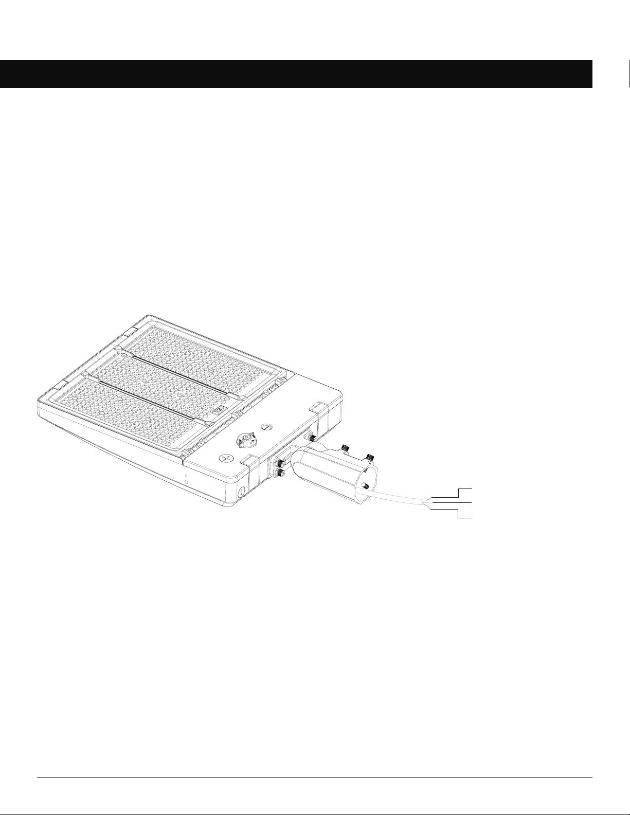
Cautions
• Fixtures must be wired in accordance with the National Electrical Code (NEC) and all applicable local codes.
• Make sure power is off at the circuit breaker before installation or maintenance.
• Proper grounding is required to ensure safety.
Notes
• Must use appropriate strain relief in accordance with local code when connecting power cord to junction box.
Green / Yellow: Ground
White / Blue: Neutral
Black / Brown: AC Line

Linmore LED Labs, Inc. | 2360 S Orange Ave, Fresno CA 93725 | 559-485-6010 | linmoreled.com | [email protected]
Ace LED Area Light (AA1) Installation Instructions
INSTALLATION
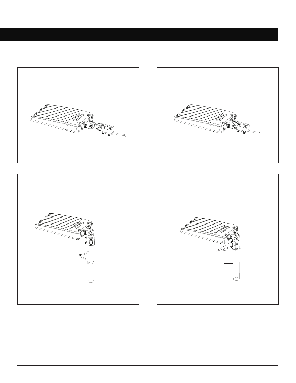
Slip Fitter
Page 9 of 12
1. Pass the wires from the xture through the
Slip Fitter bracket.
2. Install the Slip Fitter on the Bracket Base, tilt
the xture to the desired angle and tighten the
adjusting bolt.
3. Connect the wires as shown on the wiring
diagram and place them into the pole.
4. Loosen the four locking bolts and slide the Slip
Fitter over the pole. Tighten the locking bolts to
secure the xture. Re-adjust angle if needed.
Note: Adjustable angle is 0° to ±90°.
Slip Fitter Bracket
Pole
Wire
Adjusting Bolt
Pole
Green / Yellow: Ground
White / Blue: Neutral
Black / Brown: AC Line
Locking Bolts
Adjusting Bolt

Linmore LED Labs, Inc. | 2360 S Orange Ave, Fresno CA 93725 | 559-485-6010 | linmoreled.com | [email protected]
Ace LED Area Light (AA1) Installation Instructions Page 10 of 12
ACCESSORY INSTALLATIONACCESSORY INSTALLATIONINSTALLATION
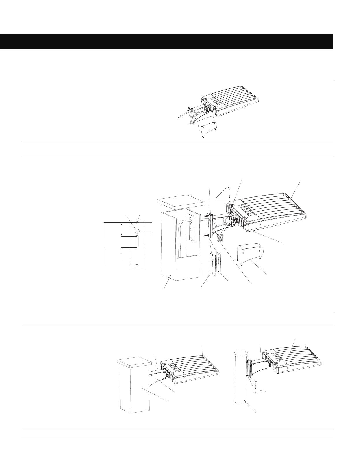
Straight Arm
1. Remove the screw on the Bracket Base,
open the side lid of the Straight Arm bracket
and pass the wires through it.
2. Fix the Straight Arm bracket to
the square bolt, pull the wire from
the pole into the junction box inside
the bracket, and connect the wires
according to the wiring diagram.
3. Place the connected wires
into the junction box inside
the bracket and reinstall
the side lid. Same as with
square pole installation,
remember to remove the
silicon plate when installing
the xture in a round pole.
Note: Adjustable angle is 0° to 35°.
Light
Side Lid
Square Pole
Straight Arm
Bracket
Silicon Plate
Light
Round Pole
Straight Arm Bracket
Square Pole
DMBracket
35°
Adjusting Bolt
Side Lid
Junction Box
Light
Silicone plate
Silicone plate
28mm
[1.1'']
Ø8.5mm
[Ø0.33'']
Ø18mm
[Ø0.71'']
45mm
[0.2'']
36mm
[1.4'']
59mm
[2.3'']
140mm
[5.5''
'']
Straight Arm
Bracket
Ø 0.71”
5.5” 1.4”
2.3”
Ø 0.33”
0.2” 1.1”
Square Bolt
Inhaltsverzeichnis
Andere Linmore LED Außenleuchte Handbücher
Beliebte Außenleuchte Handbücher anderer Marken

LIGMAN
LIGMAN BAMBOO 3 Bedienungsanleitung

Maretti
Maretti TUBE CUBE WALL 14.4998.04 Bedienungsanleitung

Maxim Lighting
Maxim Lighting Carriage House VX 40428WGOB Bedienungsanleitung

urban ambiance
urban ambiance UQL1273 Bedienungsanleitung

TotalPond
TotalPond 52238 Bedienungsanleitung

Donner & Blitzen
Donner & Blitzen 0-02661479-2 Bedienungsanleitung