
Madur MAMOS Bedienungsanleitung

MAMOS – ONLINE MONITORING SYSTEM
User guide
Version: 9.3
08/2017

www.madur.com User manual maMoS
Index
1. Introduction.......................................................................................................................................................................................................................................................... 4
2. Construction......................................................................................................................................................................................................................................................... 5
2.1. Standard equipment.....................................................................................................................................................................................................................................
2.1.1. Analyser module.................................................................................................................................................................................................................................. 6
2.1.2. Panel wit gas and electric connectors............................................................................................................................................................................................. 6
2.1.3. Display.................................................................................................................................................................................................................................................. 8
2.1.4. Work knob............................................................................................................................................................................................................................................. 9
2.1.5. SMPS – switc ed mode power supply............................................................................................................................................................................................. 10
2.1.6. MD2 gas dryer..................................................................................................................................................................................................................................... 11
2.1.7. MD3 gas dryer..................................................................................................................................................................................................................................... 12
2.1.8. Nafion gas dryer................................................................................................................................................................................................................................. 13
2.1.9. Dual-mode gas port............................................................................................................................................................................................................................ 13
2.2. Inside mamos analyser.............................................................................................................................................................................................................................. 1
2.2.1. Gas sensors........................................................................................................................................................................................................................................ 16
2.2.2. Gas pump............................................................................................................................................................................................................................................ 16
2.2.3. Ventilation valve................................................................................................................................................................................................................................. 17
2.2.4. Condensate pump.............................................................................................................................................................................................................................. 17
2.2.5. Electric terminals............................................................................................................................................................................................................................... 18
2.2.6. Communication interfaces................................................................................................................................................................................................................ 19
2.3. Optional equipment.................................................................................................................................................................................................................................... 19
2.3.1. Stationary gas probe.......................................................................................................................................................................................................................... 20
2.3.2. Heated line.......................................................................................................................................................................................................................................... 21
2.3.3. Heated filter........................................................................................................................................................................................................................................ 22
2.3.4. IP55 cabinet........................................................................................................................................................................................................................................ 23
2.3.5. Data-logger......................................................................................................................................................................................................................................... 23
2.3.5.1. Control button.............................................................................................................................................................................................................................. 24
2.3.5.2. Format SD card............................................................................................................................................................................................................................ 24
2.3.5.3. Status LED.................................................................................................................................................................................................................................... 2
2.4. Differential pressure sensor...................................................................................................................................................................................................................... 26
3. Possible working configurations...................................................................................................................................................................................................................... 27
3.1. Compact configurations............................................................................................................................................................................................................................ 27
3.2. Split configuration...................................................................................................................................................................................................................................... 27
3.3. Twin-split configuration............................................................................................................................................................................................................................. 28
3.3.1. Twin-split configuration wit one remote dryer.............................................................................................................................................................................. 28
2

www.madur.com User manual maMoS
4. Gas C annel....................................................................................................................................................................................................................................................... 29
4.1. Single gas c annel, basic configuration.................................................................................................................................................................................................. 29
4.2. AUX gas c annel........................................................................................................................................................................................................................................ 30
4.3. Hig -pressure configuration..................................................................................................................................................................................................................... 31
5. Work modes........................................................................................................................................................................................................................................................ 32
5.1. Work p ases............................................................................................................................................................................................................................................... 32
5.1.1. Initial p ases...................................................................................................................................................................................................................................... 32
5.1.1.1. Warming up.................................................................................................................................................................................................................................. 32
5.1.1.2. FirstZeroing.................................................................................................................................................................................................................................. 33
5.1.2. Ventilation........................................................................................................................................................................................................................................... 33
5.1.3. Infusion............................................................................................................................................................................................................................................... 33
5.1.4. Measurement...................................................................................................................................................................................................................................... 33
5.1.5. AUX c annel....................................................................................................................................................................................................................................... 34
5.1.6. Prestandby and Standby................................................................................................................................................................................................................... 34
5.2. Work modes................................................................................................................................................................................................................................................ 34
5.2.1. Cyclic measurements........................................................................................................................................................................................................................ 34
5.2.2. Measurements according to sc eduler............................................................................................................................................................................................ 37
5.2.3. Measurements triggered by digital input......................................................................................................................................................................................... 38
5.2.3.1. Measurements controlled by external process......................................................................................................................................................................... 39
5.2.4. Flip-Flop for Twin-Split configuration.............................................................................................................................................................................................. 39
5.2.5. Long-term, mont ly-cyclic mode...................................................................................................................................................................................................... 40
5.2.6. Long-term mode wit adjustable lengt (1-30 days)....................................................................................................................................................................... 40
5.2.7. Restrictions w en using long-term work modes............................................................................................................................................................................. 41
6. Basic Service operations................................................................................................................................................................................................................................... 41
6.1. Replacement of filter inlet in MD2 gas dryer............................................................................................................................................................................................ 41
6.2. Replacement of filter inlet in MD3 gas dryer............................................................................................................................................................................................ 42
6.3. Replacement of ydrop obic filters in gas analyser.............................................................................................................................................................................. 43
6.4. Replacement of peristaltic pump’s ose.................................................................................................................................................................................................. 44
6.5. Troubles ooting in case of “Flow too low” error.................................................................................................................................................................................... 46
3

www.madur.com User manual maMoS
1. INTRODUCTION
Mamos is a high quality, compact-size online gas monitor. Madur's best-selling product, that is constantly being improved and upgraded with a new measurement
techniques, new sensors and equipment. The device is produced using the latest technology and production techniques. Being over 1 years on the market, it has proven to meet
the most demanding requirements. Hereby, we present manual that will guide you through mamos construction, possibilities and settings. We encourage to devote some time to
reading the manual, to assure failure-free operation of the device.
Mamos online monitor has a modular construction, that allows to set the configuration of device, the best suited for user's needs. This approach also ensures the most
cost effective composition of the analyser – user pays only for the elements that are really necessary in application.
Mamos can be paired with additional equipment for sample collection and sample conditioning. Those are stationary probes (various configurations), heated lines, heated
filters, different versions of gas dryers.
Analyser can work in few configurations. By default it is compact version. Also available are split and twin-split versions, that allows to work with analyser and dryer
separated, or to measure from two different locations, i.e. before and after process or scrubber, etc.
mamos’ powerful software (and firmware) allows to individually configure how the analyser operates, and can be fully harmonised with customer process and application,
what is also possible thanks to multiple communication interfaces, digital and analogue outputs.
4
www.madur.com User manual maMoS
2. CONSTRUCTION
2.1. Standard equipment
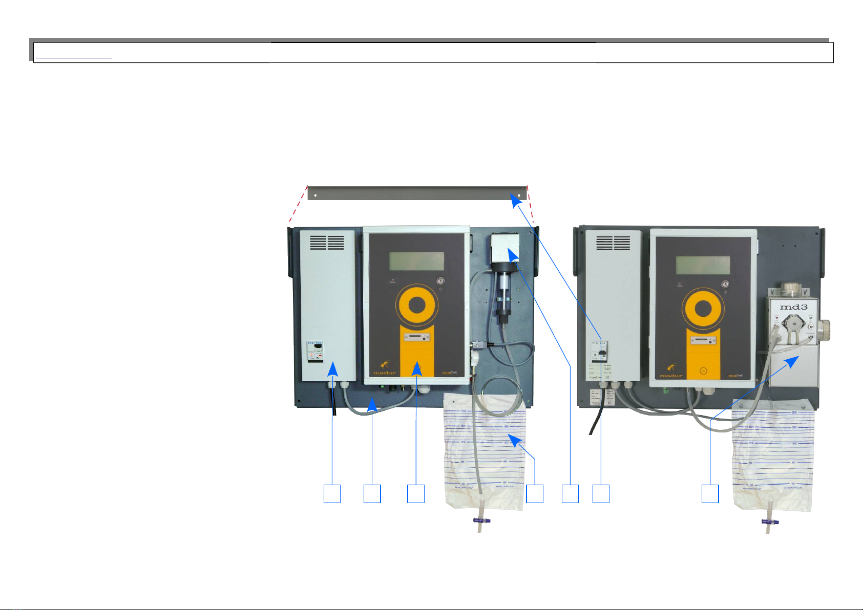
The basic configuration of mamos analyser in compact version contains:
1. Analyser module
2. SMPS – switched mode power supply –
converts 11 VAC / 230VAC to 24VDC
3. Gas dryer
a) MD2 type
b) MD3 type
4. PVC condensate bag
. Mounting plate
6. Hanger – allows for fast and convenient
installation of mamos monitor
12 3a 3b4 6
www.madur.com User manual maMoS
2.1.1. Analyser module
This is the main part of mamos online monitor. In this module gas
sensors, and other necessary components are installed. The main
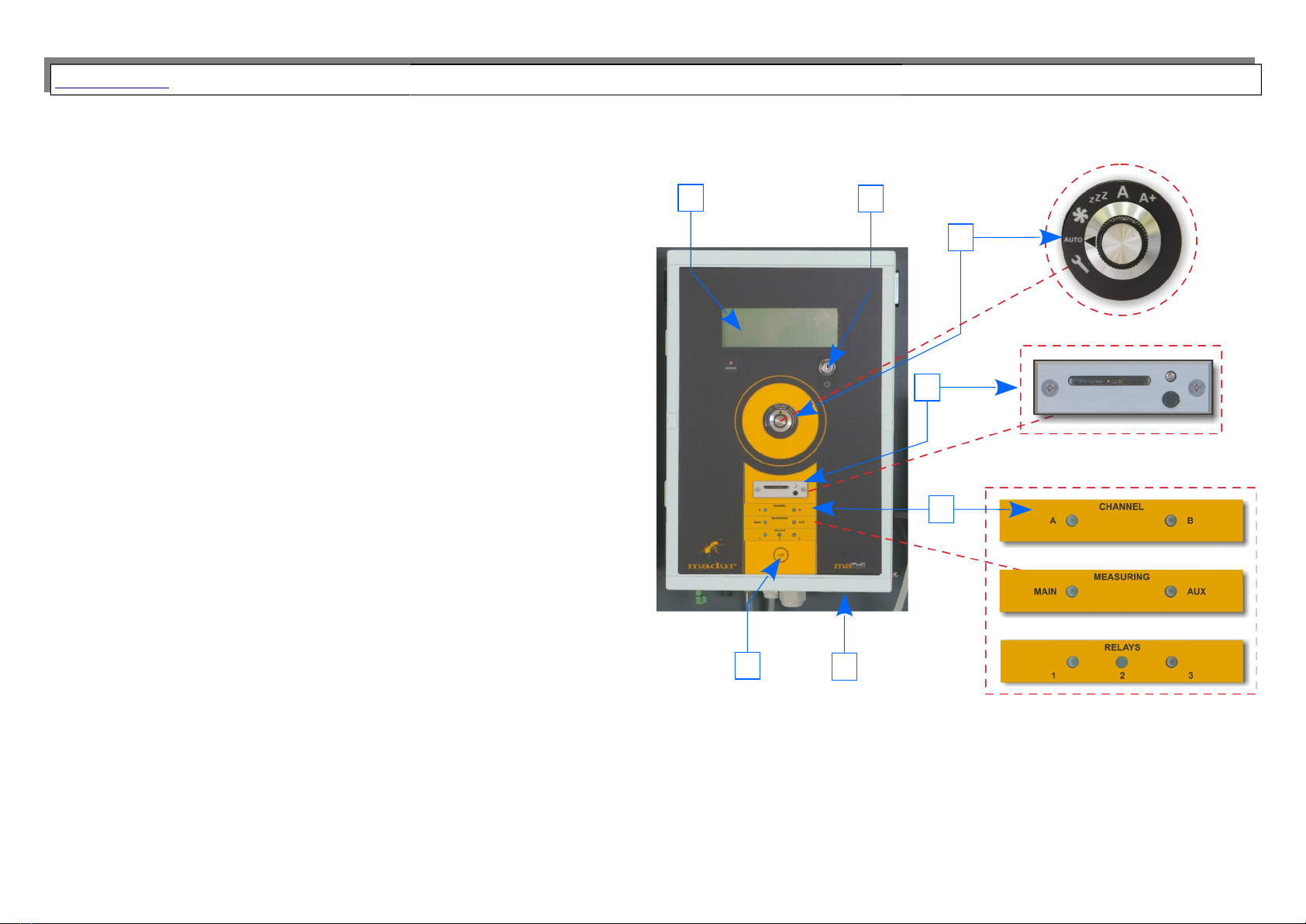
elements of the analyser's module are:
1. 4-line Display for results and important notifications
2. “LCD” function button – for simple navigation between LCD screens
3. On/Off key
4. Optional Data-logger module with SD card for collection of measurement
results
. Work knob
6. LED status diodes
(installed for corresponding device configuration)
7. Panel with gas and electric connectors (at the bottom)
8. Peristaltic pump (only for analyser with MD2 dryer) – not presented in the
picture
2.1.2. Panel with gas and electric connectors
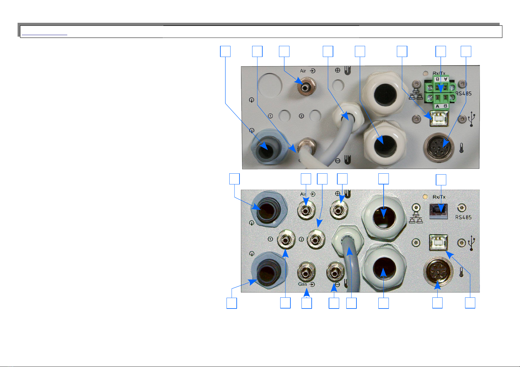
All gas and electric connections to the analyser are located on one panel, installed in the bottom part of the analyser. Depending on the configuration of the device,
connections may differ. For convenience, all of them are described with icons and, if necessary with text. Below we describe the typical gas and electric connectors.
6
13
2
44
66
7
www.madur.com User manual maMoS
Connectors for basic mamos configuration:
1. Gas outlet – waste gas
2. Gas inlet (from the gas dryer) (Dual-mode gas port)
3. Fresh air inlet (ventilation) (Dual-mode gas port)
4. Power supply cable (from SMPS)
. Cables' pass
6. USB B connector – connection with PC (with madur software)
7. RS48 connector – connection with PC (with madur software)
8. Thermocouple connector
Connectors for Hi-press version of analyser with 2 gas channels:
9. Waste outlet from AUX gas channel
(for analyser with 2 gas channels)
10. Gas inlet from gas dryer (High-pressure configuration)
11. Gas outlet to gas dryer (High-pressure configuration)
12. Differential pressure port (+)
13. Differential pressure port (–)
14. LAN connector – connection with PC within LAN network only
(with madur software) – replaces RS48 connector (7)
On the bottom part of mamos analyser, besides the connectors panel, there is also a separate MODBUS RTU (RS48 ) connector.
7
1
14
9
10 2
3 11 12
13 4
8 6
1 2 3 4 6 7 8
www.madur.com User manual maMoS
2.1.3. Display
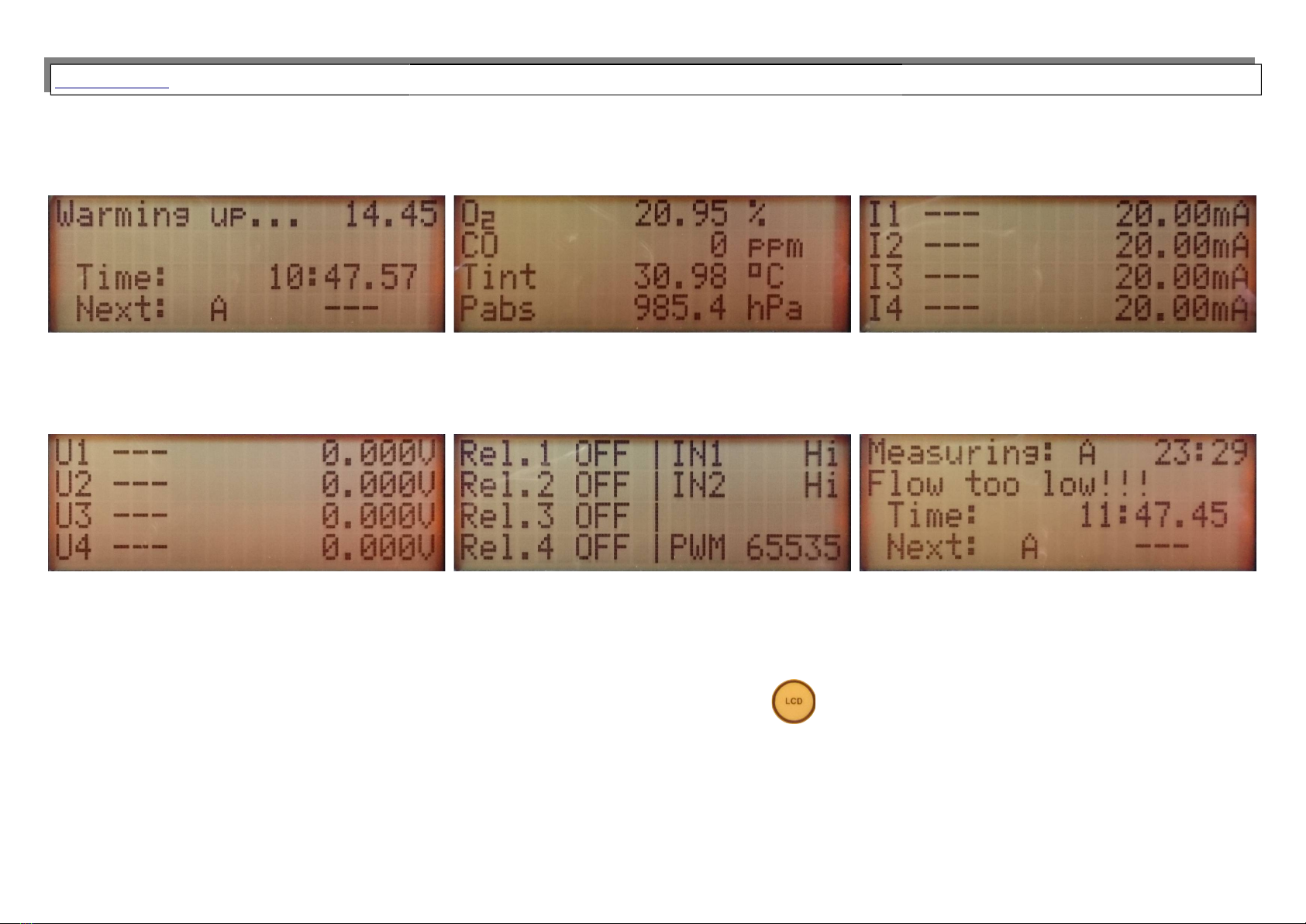
Mamos has one large display to present results, but also to notify user with important information, current work phase, status of analogue outputs, potential errors, etc.
Warming up will last for another 14 min. 4 sec.
Current time 10:47: 7
The next measurement will be performed from place A (for
twin split configuration)
Screen with results. From mamos PC program user can
individually define what values will be presented on
screen. It is possible to define 2 screens (8 different
values).
Screen with status of current analogue outputs.
Screen with status of voltage analogue outputs. Screen with status of relays, digital inputs and PWM
output.
Mamos is in measurement phase (from gas source A), but
flow through the analyser is below threshold value, and
mamos reports an error: Flow too low!!! (See chapter 6. )
Mamos switches through its screens automatically. User can go to the screen of interest using LCD button located in the bottom of analyser’s below display.
8
www.madur.com User manual maMoS
2.1.4. Work knob
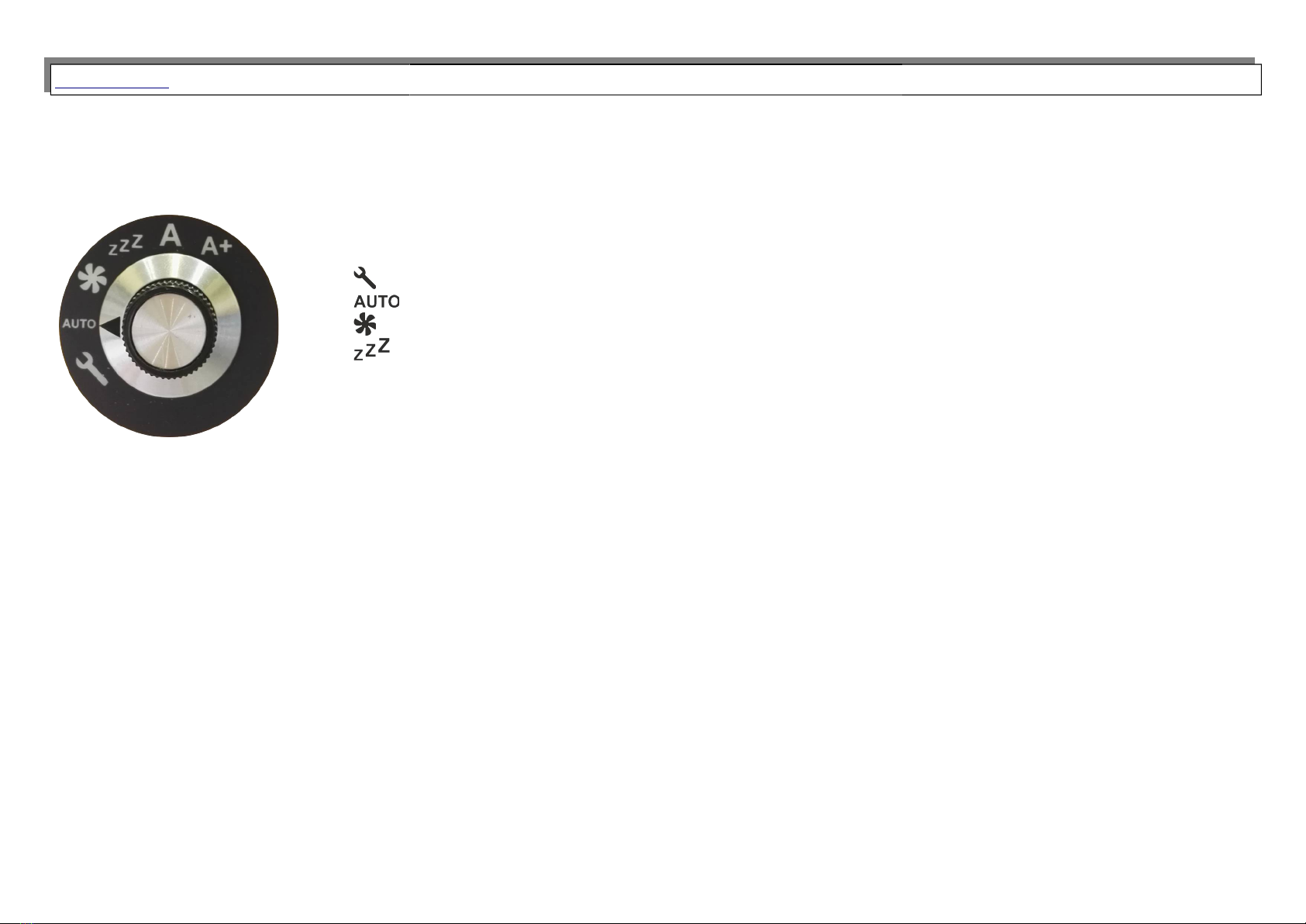
Since 2017 work knob is a standard equipment of every mamos analyser. It ease the performance of service maintenance or random check of
analyer’s work. Knob allows to manually select analyser’s work phase and it overrides automatic selection.
More information on selected work modes can be found in chapter . Available selections:
•Service mode (for madur internal use)
•Analyser works according to currently selected program settings
•Ventilation
•Standby - .1.6
•AEnabled Measurements from channel A
•A+ Enabled channel A including auxiliary channel (available only when analyser is equipped with AUX channel)
•BEnabled measurement from channel B (available only for analyser in Twin-split configuration)
•B+ Enabled channel A including auxiliary channel (available only when analyser is in Twin-split configuration and is equipped
with AUX channel)
9
www.madur.com User manual maMoS
2.1.5. MP – switched mode power supply
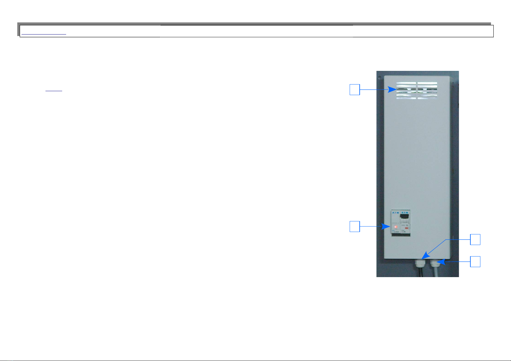
Madur provides power supply module that converts mains (either 230 VAC or 11 VAC) to 24VDC required by
mamos. SMPS provides not only for the analyser but also for gas dryer and for heated hose steering relay. In case of
Split configuration and Twin-split configuration, every remote MD3 dryer is equipped with its own SMPS module.
1. SMPS cover
2. Power switch with fuse – depending on version there are 1÷2 fuses (analyser + MD3 dryer, heated hose)
3. Mains cable
4. Supply cable – depending on version there are 1÷3 supply cables (for: analyser, MD3 dryer, heated hose)
10
1
2
3
4
Andere Handbücher für MAMOS
1
Inhaltsverzeichnis
Andere Madur Messgerät Handbücher


