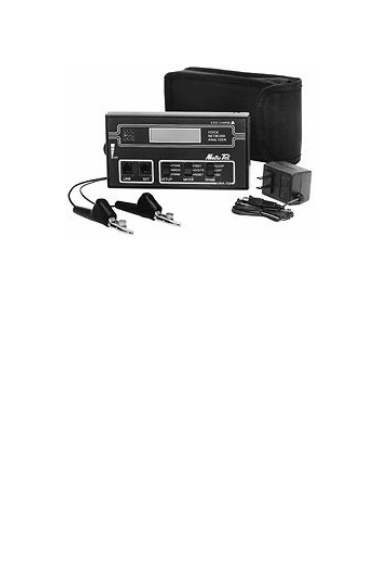
METROTEC VNA-70A Bedienungsanleitung

Voice Network Analyzer
MODEL VNA-70A
Instruction Manual
P/N 82-70-027
February 2004
1
StockCheck.com

This page is intentionally blank.
2
StockCheck.com

TABLE OF CONTENTS
1.0 INTRODUCTION
2.0 GENERAL DESCRIPTION
3.0 CONTROLS
4.0 OPERATION
4.1 BATTERY TEST
4.2 BRIDGING AND TERMINATING
4.3 VOICE NETWORK ANALYZER
4.3.1DC VOLTS
4.3.2DC MILLIAMPERES
4.3.3DBm
4.3.4AC VOLTS
4.3.5FREQUENCY
4.3.6TONE GENERATOR
4.3.7OHMS
4.4.DIGIT DISPLAY
4.4.1.OPERATION
4.4.2.DIAL PULSE LEVEL SELECT
4.5.MONITOR SPEAKER
5. POWER SOURCE
6. SPECIFICATIONS
7. APPLICATION NOTES
8. WARRANTY
3
StockCheck.com

1.0 INTRODUCTION
This document provides information on the Model VNA-70A Voice
Network Analyzer Test Set. Included are descriptions of the instrument
controls, functions, specifications and applications. The information is
designed for test engineers and technicians.
2.0 GENERAL DESCRIPTION
The VNA70-A is a comprehensive telecom test instrument which
offers several modes of operation designed specifically for the telecom
environment. Model 70A is an enhanced version of the earlier Model 70
with the addition of Ohms test capability.
The test set acts as a DVOM, a frequency counter, oscillator, dialed
digit display and milliammeter. This unique set of functions are selected to
allow thorough troubleshooting of the local telephone loop and the premise
equipment connected to it.
The instrument is battery powered. It connects to the telephone line
via modular jacks and an alligator clip cordset. All results are shown on a
single high-contrast screen for simple and speedy usage. Measurements
are autoranging and true RMS. Functions include:
A. VOICE NETWORK TEST -- measures and simultaneously displays the
following phone line parameters:
1. DC Voltage
2. DC loop current
3. DC polarity
4. AC signals in either dBm or AC volts
5. Signal frequency
In a separate mode, the VNA-70A measures resistance:
6. Ohms in lop and DC
B. TONE GENERATOR -- generates a 1004 Hz sinewave.
C. DIGIT DISPLAY -- displays numbers as they are dialed.
D. AUDIO MONITOR -- allows input signals to be monitored via a built-in
speaker.
In connection with these features, the VNA-70A may be operated in
either of two modes:
LINE BRIDGING -- allows measurements to be made without loading
the phone line. Input signals may also be monitored via the built-in
speaker
LINE TERMINATING -- applies a precise 600 Ohm AC load to the line
while presenting a 50 to 300 Ohm effective DC resistance.
4
StockCheck.com

3. CONTROLS
A. On/Off/Volume Control
B. Telephone Line Jack
C. Butt Set/CPE Jack
D. Setup Switch
E. Test Mode Switch
F. OHMS Switch
G. Audio Monitor Speaker
H. Display Screen; Super-Twist high contrast
I. Battery Charging Jack
J. Dial Pulse LEVEL SELECT
(Located inside battery compartment)
5
StockCheck.com

Figure 3-1 Instrument Controls
4. OPERATION
4.1 Battery Test
When power is first turned on and the MODE switch is in the TEST
(UP) position, the VNA-70A will automatically enter the Battery Test mode.
During this brief period, it will measure the voltage of its own battery and
indicate this value on the Display Screen. The condition of the battery may
also be monitored at any time by observing the position of the cursor line
along the bottom of the display. The cursor begins on the right-hand side
of the screen with a new or fully charged battery; as the battery runs down,
the cursor moves towards the left. Replace the battery (or recharge if
rechargeable option is installed) when the cursor reaches the left-hand side
of the screen, or if the Battery Test at power-on reads below 6.5 Volts.
4.2 Bridging and Terminating
Using the SETUP switch, either a Line Terminating or a Line Bridging
test setup may be selected. The Line Terminating setup is equivalent to an
“off hook” condition on the phone line, and is selected by setting the switch to
the TERM (down) position. In this setup the VNA-70A presents a fixed 600
Ohm AC load and a variable 50 to 300 Ohm DC load to the line. The Line
Bridging test setup is the equivalent of an “on hook” condition on the phone
line, and is selected by setting the SETUP switch to the BRDG (center)
position. In this case the VNA-70A presents a high-impedance to the line.
6
StockCheck.com

4.3 Voice Network Testing
The Voice Network Test mode is entered by placing the MODE switch in
the TEST (up) position. To make measurements:
a. Insert the modular plug on the test lead into the LINE jack.
b. Connect the test lead clips to telephone line Tip and Ring.
c. Plug a telephone or butt-set into the SET jack.
The following information will appear on the screen:
4.3.1 DC Voltage appears in the upper left-hand section of the screen.
A “+” or a “-“ precedes the voltage value shown to indicate its polarity.
The VNA-70A resolves voltage to the nearest ½ volt, therefore the
fractional DC voltage value is always a “.0” or a “.5”. An over range
condition is indicated by a ▲▲▲ reading.
4.3.2 DC Loop Current appears in the lower left-hand section of the
screen. A “+” or a “-“ precedes the current value shown to indicate its
polarity. The VNA-70A resolves current to the nearest ½ mA, therefore
the fractional DC current value is always a “.0” or a “.5”. An over range
condition is indicated by a ▲▲▲ reading.
_______________________________________________________
CAUTION
_______________________________________________________
OVERRRANGING THE DC MILLIAMMETER SECTION OF THE
VNA-70 FOR EXTENDED PERIODS MAY RESULT IN INTERNAL
DAMAGE.
4.3.3 dBm is displayed in the upper right-hand section of the screen.
With no input signal, an under range reading, indicated by▼▼▼,
is given. For signal inputs between -44 dBm and +4 dBm, the
“dB” mode is automatically selected. DB values are logarithmic in
scale; therefore resolution decreases with signal level.
This may be visualized by recalling the familiar scale of an analog
dB meter; indications are farther apart on the right-hand side and
get closer together toward the left-hand side. See the
SPECIFICATIONS section of this manual for dBm resolution at
various input levels.
4.3.4 AC Voltage replaces the dB indication when the input level is
above +4 dBm. In the AC Volts mode, readings may be taken up
to 125 Volts. An over range condition is indicated by a ▲▲▲
7
StockCheck.com

reading. Both DBm and AC Volts measurements are made using
the True RMS conversion method and will give correct readings
even if distortion, multiple frequencies or noise are present.
4.3.5 Frequency of the input signal appears in the lower right=hand
section of the screen. The VNA-70A resolves frequency to the
nearest cycle. An over range condition is indicated by a ▲▲▲
reading. Note: due to noise, it is normal for a low frequency
reading to sometimes be displayed even with no input.
4.3.6 Tone Generator mode is entered by pushing the SETUP switch
up to TONE position. A “1004 Hz TONE” message appears on
the screen indicating selection of this mode. The sine wave
output should be taken from the LINE jack. Line termination is
maintained while the tone is on, making it an ideal reference tone
for transmission loss measurements. Tone output is at 0.0 dBm.
It also makes a handy “buzz box” for identifying wire pairs in multi-
line cables.
4.3.7 Resistance measurement to the nearest 100 Ohms is possible in
two different modes, depending upon the selection of the Ohms
switch:
LOOP OHMS is selected by moving the Ohms switch to the LOOP
(up) position. This mode gives the effective resistance of a
powered-up, or “Wet loop” by measuring voltage and current, then
calculating the resistance and displaying it on the screen. To use
this Feature:
a. Connect the phone line to the LINE jack, leaving the SET jack
unused.
b. Move the Ohms switch from the OFF (center) position to the
LOOP position.
c. Follow the prompts on the screen, first switching the SETUP
switch to BRDG, then to TERM. The calculated Ohms value
will appear on the display.
DC OHMS is selected by moving the Ohms switch to the DC (down)
position. The clip lead set should be connected to the LINE jack.
While the SET jack is left unused. The test lead clips may be
connected to measure the resistance of any un-powered, or “dry”
circuit.
4.4 Digit Display
4.4.1. Placing the MODE switch in the DIGITS (center) position selects
the Digit Display function. A flashing cursor in the upper left-hand corner
of the screen indicates selection of this mode. In most cases, it is
desirable to select the Line Bridging mode while using this feature.
To use the Digit Display:
8

StockCheck.com

a. Insert the modular plug on the test lead into the LINE jack.
b. Connect the test lead clips to telephone line Tip and Ring.
c. Digits will appear on the screen at the location of the cursor. When
the first line of the display is full, the cursor will “roll-over” to the
second line. When the second line is full, the cursor will “roll” back
to the beginning of the first line. Therefore, if a digit string longer
than thirty-two digits in length is received, the last thirty-two digits
will be displayed.
d. Momentarily pushing the MODE switch down to the RESET position
will clear the display.
4.4.2. The VNA-70A provides two different sensitivity levels for dial pulse
detection. A switch located inside the battery compartment allows
selection of the level most appropriate to a given application. To
set the switch, remove the battery door on the back of the unit, and
hold it so that the battery compartment is to your left.
If the VNA-70A is to read pulse digits at a Central Office or at a D.I.D.
terminal, set the switch to the UP position.
If the VNA-70A is to be used in PBX systems having a 24-Volt battery
system, set the switch to the down position.
For digit monitoring at customer premises on standard 48-Volt
systems, either setting will work although it is generally preferable
to keep the switch in the down position unless CO/DID capability is
specifically required.
4.5. Monitor Speaker
The VNA-70A is equipped with a built-in monitor speaker, which may
be used at any time. Set its volume to the desired level using the
ON/OFF/VOLUME thumbwheel.
9
StockCheck.com

5. POWER SOURCE
The VNA-70A is equipped with a 9-Volt rechargeable Ni-Cad battery.
When the battery runs down, recharge by inserting the plug from the
recharging transformer into the Battery Charger jack on top of the VNA-70A
and plugging the charging transformer into a 110 to 120-Volt AC source.
Recharging time is approximately 12 hours.
The VNA-70A may also be operated from a standard 9-Volt alkaline
battery. The battery is accessed by sliding off the removable cover on the
back of the case. CAUTION: DO NOT ATTEMPT TO USE THE
CHARGING TRANSFOMER IF AN ALKALINE BATTERY IS INSTALLED
IN THE VNA-70A. USE THE CHARGING TRANSFORMER ONLY WHEN
THE RECHARGEABLE NI-CAD BATTERY IS INSTALLED.
6. SPECIFICATIONS
Parameter Min Typ Max Unit
VOICE NETWORK ANALYZER:
DC Volts:
Range +/-1 +/-99.5 Volts DC
Resolution 0.5 Volt
Accuracy +/-1.0 % of FS
DC Milliamps:
Range +/-1 +/-99.5 mA DC
Resolution 0.5 mA
Accuracy +/-1.0 % of FS
AC Volts:
Range 3 125 Volts AC
Resolution 1 Volt
Accuracy +/-2.0 % of FS
Frequency Range 16 1K Hz
Conversion
Method True RMS
Decibels:
Range -44 +4 DBm
Resolution and
Accuracy:
-20 to +4 dBm 0.5 dB
-30 to -20 dBm 1.0 dB
-34 to -30 dBm 2.0 dB
-38 to -34 dBm 4.0 dB
-44 to -38 dBm 6.0 dB
Frequency Range 30 8K Hz
10
StockCheck.com
Inhaltsverzeichnis
Andere METROTEC Messgerät Handbücher