
Olympus GLIDER Bedienungsanleitung

DMTA029-01EN — Rev. E
December 2017
GLIDER
Two-Axis Flat Panel Scanner
User’s Manual
This instruction manual contains essential information on how to use this Olympus product safely and effectively.
Before using this product, thoroughly review this instruction manual. Use the product as instructed.
Keep this instruction manual in a safe, accessible location.

Olympus Scientific Solutions Americas, 48 Woerd Avenue, Waltham, MA 02453, USA
Copyright © 2007, 2014, 2016, 2017 by Olympus. All rights reserved. No part of this
publication may be reproduced, translated, or distributed without the express written
permission of Olympus.
This document was prepared with particular attention to usage to ensure the accuracy of the
information contained therein, and corresponds to the version of the product manufactured
prior to the date appearing on the title page. There could, however, be some differences
between the manual and the product if the product was modified thereafter.
The information contained in this document is subject to change without notice.
Part number: DMTA029-01EN
Rev. E
December 2017
Printed in Canada
All brands are trademarks or registered trademarks of their respective owners and third
party entities.

DMTA029-01EN, Rev. E, December 2017
Table of Contents iii
Table of Contents
Labels and Symbols ........................................................................................... 1
Important Information — Please Read Before Use ..................................... 3
Intended Use .......................................................................................................................... 3
Instruction Manual ................................................................................................................ 3
Loose Parts .............................................................................................................................. 4
Scanner Compatibility .......................................................................................................... 4
Presence of Visual Interferences or Phantom Spots ......................................................... 5
Safety Symbols ....................................................................................................................... 5
Safety Signal Words ............................................................................................................... 6
Note Signal Words ................................................................................................................. 7
Safety ....................................................................................................................................... 7
Warnings ................................................................................................................................. 7
Equipment Disposal .............................................................................................................. 8
CE (European Community) ................................................................................................. 8
WEEE Directive ...................................................................................................................... 8
Warranty Information ........................................................................................................... 9
Technical Support .................................................................................................................. 9
Introduction ...................................................................................................... 11
1. Overview ..................................................................................................... 13
2. Scanner Assembly and Setup .................................................................. 17
2.1 Assembling the Scanner ........................................................................................... 17
2.2 Part Replacement and Adjustment ........................................................................ 18
2.2.1 Replacing a Mounting Pod ........................................................................... 18
2.2.2 Installing a Vacuum Generator with Pods ................................................. 19
2.2.3 Adjusting the Orientation of the Probe Holder ......................................... 28

DMTA029-01EN, Rev. E, December 2017
Table of Contentsiv
2.2.4 Installing Springs on the Bearing Arm ........................................................ 30
2.2.5 Replacing a Conventional Ultrasonic Transducer ..................................... 33
2.2.6 Replacing a Phased Array Probe ................................................................. 35
2.2.7 Changing an Encoder .................................................................................... 37
2.2.8 Changing the Length of an Axis .................................................................. 38
2.3 Scanner Installation on the Inspection Surface ..................................................... 41
2.3.1 Installing a Scanner with Suction-Cup Pods .............................................. 41
2.3.2 Installing a Scanner with Magnetic Pods .................................................... 44
2.4 Setting Up the Scanner for Inspection .................................................................... 46
3. Operating the Scanner .............................................................................. 49
4. Specifications .............................................................................................. 53
5. Accessories and Spare Parts ..................................................................... 57
5.1 Yokes ........................................................................................................................... 57
5.2 Couplant-Feed Units ................................................................................................ 58
5.3 Connector Reference ................................................................................................. 59
5.4 Spare Parts .................................................................................................................. 59
6. Maintenance ................................................................................................ 65
6.1 Preventive Maintenance ........................................................................................... 65
6.2 Unit Cleaning ............................................................................................................. 65
List of Figures ................................................................................................... 67
List of Tables ..................................................................................................... 69
Index ................................................................................................................... 71

DMTA029-01EN, Rev. E, December 2017
List of Abbreviations v
List of Abbreviations
A.M. according to model
CE European Community
EC eddy current
ECA eddy current array
FSW friction stir weld
ID internal diameter
N/A not applicable
NL normal liters
OD outside diameter
OEM original equipment manufacturer
P/N part number
PA phased array
SCFM standard cubic feet per minute
UT ultrasonic testing
WEEE waste electrical and electronic equipment

DMTA029-01EN, Rev. E, December 2017
List of Abbreviationsvi
DMTA029-01EN, Rev. E, December 2017
Labels and Symbols 1
Labels and Symbols
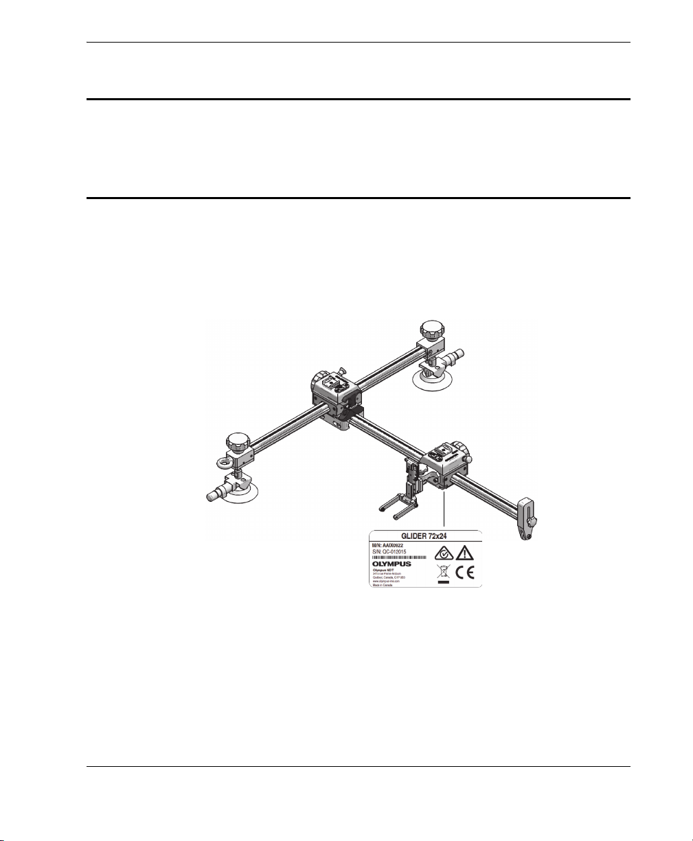
Safety-related labels and symbols are attached to the GLIDER scanner at the location
shown in Figure i-1 on page 1, with contents listed in Table 1 on page 2. If any or all of
the labels or symbols are missing or illegible, please contact Olympus.
Figure i‑1 Location of label on the GLIDER scanner
Rating label

DMTA029-01EN, Rev. E, December 2017
Labels and Symbols2
Table 1 Content of the rating label
Content
M/N The model number is an eight (8) digit number.
S/N The serial number is an eight (8) digit number.
The regulatory compliance mark (RCM) label indicates that
the product complies with all applicable standards, and has
been registered with the Australian Communications and
Media Authority (ACMA) for placement on the Australian
market.
The warning symbol indicates that the user must read the
user’s manual in order to find out the nature of the potential
hazards and any actions to avoid them.
The WEEE symbol indicates that the product must not be
disposed of as unsorted municipal waste, but should be
collected separately.
The CE marking is a declaration that this product conforms to
all the applicable directives of the European Community. See
the Declaration of Conformity for details. Contact your Olympus
representative for more information.
The direct current symbol.

DMTA029-01EN, Rev. E, December 2017
Important Information — Please Read Before Use 3
Important Information — Please Read Before Use
Intended Use
The GLIDER scanner is designed to perform nondestructive inspections on industrial
and commercial materials.
Do not use the GLIDER scanner for any purpose other than its intended use. It must
never be used to inspect or examine human or animal body parts.
Instruction Manual
This instruction manual contains essential information on how to use this Olympus
product safely and effectively. Before using this product, thoroughly review this
instruction manual. Use the product as instructed.
Keep this instruction manual in a safe, accessible location.
Some of the details of components illustrated in this manual may differ from the
components installed on your instrument. However, the principles remain the same.
WARNING
IMPORTANT

DMTA029-01EN, Rev. E, December 2017
Important Information — Please Read Before Use4
Loose Parts
The user is responsible for ensuring that no scanner parts have come loose or are lost
in critical mechanisms being inspected or maintained, especially in the case of aircraft.
Conduct a proper inspection before and after use to prevent foreign-object debris
(FOD) that could potentially cause equipment damage, injuries, or loss of life.
Scanner Compatibility
The GLIDER scanner is compatible with the Olympus ancillary equipment listed in
Table 2 on page 4.
Always use equipment and accessories that meet Olympus specifications. Using
incompatible equipment could cause equipment malfunction and/or damage, or
human injury.
Table 2 Ancillary equipment
Equipment Description
OmniScan PA and FOCUS LT Several types of phased array instrument model
can be used (may require one of the encoder cable
adaptors listed below).
Phased array probe and wedge Several models used. See Table 6 on page 57 for
optional holder models required according to
wedge models.
WARNING
CAUTION
Inhaltsverzeichnis
Andere Olympus Scanner Handbücher

Olympus
Olympus HST-X04 Bedienungsanleitung

Olympus
Olympus COBRA Bedienungsanleitung

Olympus
Olympus HST-Lite Bedienungsanleitung

Olympus
Olympus ChainSCANNER Bedienungsanleitung

Olympus
Olympus HSMT-Flex Bedienungsanleitung

Olympus
Olympus HST-X04 Bedienungsanleitung

Olympus
Olympus SteerROVER Bedienungsanleitung

Olympus
Olympus HSMT-Compact Bedienungsanleitung
Olympus
Olympus FlexoFORM Bedienungsanleitung


