Onicon D-1401 Betriebsanleitung
Andere Onicon Messgerät Handbücher

Onicon
Onicon F-1000 SERIES Bedienungsanleitung

Onicon
Onicon F-5200 Betriebsanleitung

Onicon
Onicon F-4600 Series Betriebsanleitung

Onicon
Onicon F-3200 Series Original Betriebsanleitung

Onicon
Onicon SeaMetrics EX90 Bedienungsanleitung

Onicon
Onicon F-2600 Series Betriebsanleitung

Onicon
Onicon SYSTEM-30 Betriebsanleitung

Onicon
Onicon FP-4400 Original Betriebsanleitung

Onicon
Onicon F-4600 Series Betriebsanleitung

Onicon
Onicon System-10 BTU Meter Betriebsanleitung

Onicon
Onicon System-10 BTU Meter Bedienungsanleitung

Onicon
Onicon F-4300 Original Betriebsanleitung

Onicon
Onicon FT-3000 Series Bedienungsanleitung

Onicon
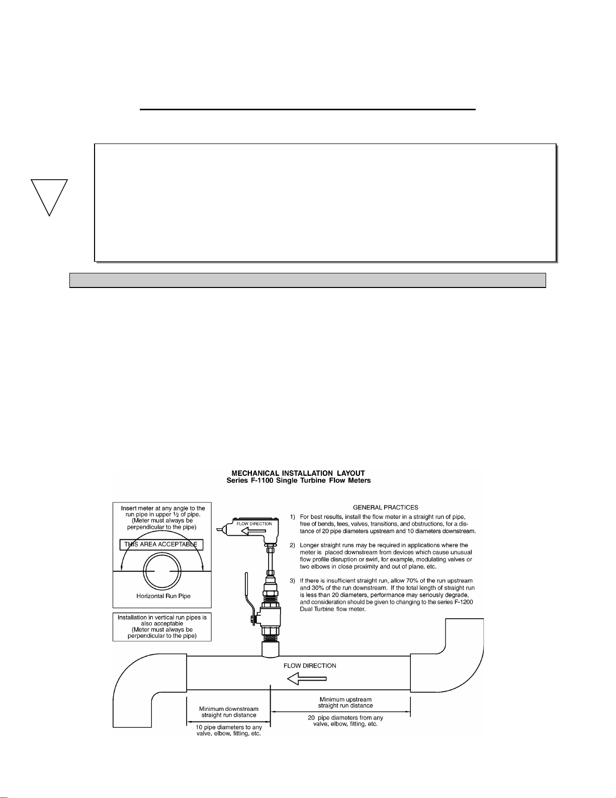
Onicon F-1100 Series Betriebsanleitung

Onicon
Onicon Vortex Flow Meter F-2200 Series Betriebsanleitung

Onicon
Onicon D-100 Bedienungsanleitung

Onicon
Onicon F-5000 Betriebsanleitung

Onicon
Onicon FT-3400 Betriebsanleitung

Onicon
Onicon F-1000 SERIES Konfigurationshandbuch

Onicon
Onicon SYSTEM-40 Betriebsanleitung