
Pembina BP2900 Bedienungsanleitung
Digital Flow Monitor
BP2900
User Manual

Digital Flow Monitor, BP2900
Page ii April 2021

CONTENTS
Introduction. . . . . . . . . . . . . . . . . . . . . . . . . . . . . . . . . . . . . . . . . . . . . . . . . . . 5
Scope of This Manual 6
Unpacking and Inspection 6
Safety 6
Terminology and Symbols 6
Considerations 6
Electrical Symbols 7
Installation 7
Connecting the BP2900 Monitor to a Frequency Output Device 7
Power Connections . 9
Standard. . . . . . . . . . . . . . . . . . . . . . . . . . . . . . . . . . . . . . . . . . . . . . . . . . 9
Operating the Monitor 10
Buttons. . . . . . . . . . . . . . . . . . . . . . . . . . . . . . . . . . . . . . . . . . . . . . . . . . 10
Modes of Operation. . . . . . . . . . . . . . . . . . . . . . . . . . . . . . . . . . . . . . . . . . 11
Programming Using Frequency Output Turbine Flow Meters . . . . . . . . . . . . . . . 11
Enter Programming Mode. . . . . . . . . . . . . . . . . . . . . . . . . . . . . . . . . . . . . . 11
Menu Structure. . . . . . . . . . . . . . . . . . . . . . . . . . . . . . . . . . . . . . . . . . . . . . . . 12
Liquid. . . . . . . . . . . . . . . . . . . . . . . . . . . . . . . . . . . . . . . . . . . . . . . . . . . 12
Advanced I/O Liquid . . . . . . . . . . . . . . . . . . . . . . . . . . . . . . . . . . . . . . . . . 14
Gas . . . . . . . . . . . . . . . . . . . . . . . . . . . . . . . . . . . . . . . . . . . . . 16
Advanced I/O Gas 18
Liquid (Solar Powered) . . . . . . . . . . . . . . . . . . . . . . . . . . . . . . . . . . . . . . . . 20
Gas (Solar Powered). . . . . . . . . . . . . . . . . . . . . . . . . . . . . . . . . . . . . . . . . . 22
Programming. . . . . . . . . . . . . . . . . . . . . . . . . . . . . . . . . . . . . . . . . . . . . . . . . 24
Liquid. . . . . . . . . . . . . . . . . . . . . . . . . . . . . . . . . . . . . . . . . . . . . . . . . . . 24
Gas . . . . . . . . . . . . . . . . . . . . . . . . . . . . . . . . . . . . . . . . . . . . . 37
Return to Run Mode . . . . . . . . . . . . . . . . . . . . . . . . . . . . . . . . . . . . . . . . . 37
Troubleshooting Guide. . . . . . . . . . . . . . . . . . . . . . . . . . . . . . . . . . . . . . . . . . . 38
User Manual
Page iii
April 2021

Default K-Factor Values. . . . . . . . . . . . . . . . . . . . . . . . . . . . . . . . . . . . . . . . . . . 38
Battery Replacement 39
K-Factors Explained 40
Calculating K-factors 40
Modbus Interface . . . . . . . . . . . . . . . . . . . . . . . . . . . . . . . . . . . . . . . . . . . . . . 43
Modbus Register / Word Ordering. . . . . . . . . . . . . . . . . . . . . . . . . . . . . . . . . 44
Specications. . . . . . . . . . . . . . . . . . . . . . . . . . . . . . . . . . . . . . . . . . . . . . . . . 47
Part Number Construction. . . . . . . . . . . . . . . . . . . . . . . . . . . . . . . . . . . . . . . . . 48
Mounting Options and Dimensions. . . . . . . . . . . . . . . . . . . . . . . . . . . . . . . . . . . 49
Meter Mount . 49
Remote Mount . . . . . . . . . . . . . . . . . . . . . . . . . . . . . . . . . . . . . . . . . . . . . 49
Handheld . . . 50
Swivel Mount. . . . . . . . . . . . . . . . . . . . . . . . . . . . . . . . . . . . . . . . . . . . . . 51
Digital Flow Monitor, BP2900
Page iv April 2021

Introduction
Page 5
April 2021
INTRODUCTION
The BP2900 flow monitor incorporates state- of-the-art, digital signal processing technology,
designed to provide exceptional flexibility at a very affordable price Though designed for
use with Pembina Controls flow sensors, this monitor can be used with almost any flow
sensor producing a low amplitude AC output or contact closure signal
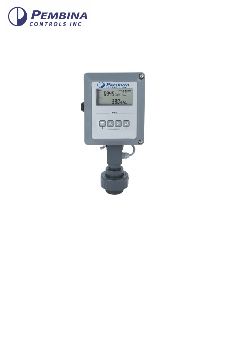
Figure 1: BP2900 Flow monitor (NEMA 4X)
This monitor can accept low-level frequency input signals typically found in turbine flow
sensors The output signal for these types of sensors is a frequency proportional to the
rate of flow The BP2900 monitor uses the frequency information to calculate flow rate and
total flow Through the use of the programming buttons, you can select rate units, total
units and unit time intervals among other functions If required, the monitor can easily be
re-configured in the field Finally, you can choose between simultaneously showing rate
and total, or alternating between rate and grand total
BP2900

Scope of This Manual
Page 6 April 2021
SCOPE OF THIS MANUAL
This manual is intended to help you get the BP2900 flow monitor up and running quickly
IMPORTANT
Read this manual carefully before attempting any installation or operation. Keep the manual
accessible for future reference.
UNPACKING AND INSPECTION
Upon opening the shipping container, visually inspect the product and applicable
accessories for any physical damage such as scratches, loose or broken parts, or any other
sign of damage that may have occurred during shipment
NOTE: If damage is found, request an inspection by the carrier’s agent within 48 hours of
delivery and file a claim with the carrier. A claim for equipment damage in transit
is the sole responsibility of the purchaser.
SAFETY
Terminology and Symbols
Indicates a hazardous situation, which, if not avoided, is estimated to
be capable of causing death or serious personal injury.
Indicates a hazardous situation, which, if not avoided, could result in
severe personal injury or death.
Indicates a hazardous situation, which, if not avoided, is estimated to
be capable of causing minor or moderate personal injury or damage
to property.
Considerations
The installation of the BP2900 monitor must comply with all applicable federal, state,
and local rules, regulations, and codes
WARNING
EXPLOSION HAZARD - SUBSTITUTION OF COMPONENTS MAY IMPAIR SUITABILITY FOR
CLASS I, DIVISION 2.
AVERTISSMENT
RISQUE D’EXPLOSION - LA SUBSTITUTION DE COMPOSANTS PEUT RENDRE
CEMATÉRIEL INACCCEPTABLE POUR LES EMPLACEMENTS DE CLASSE I, DIVISION 2.
WARNING
DO NOT CONNECT OR DISCONNECT EITHER POWER OR OUTPUTS UNLESS THE AREA IS
KNOWN TO BE NON-HAZARDOUS.

Installation
Page 7
April 2021
AVERTISSMENT
RISQUE D’EXPLOSION. NE PAS DÉBRANCHER TANT QUE LE CIRCUIT EST SOUSTENSION,
À MOINS QU’LL NE S’AGISSE D’UN EMPLACEMENT NON DANGEREUX.
MPORTANTI
Not following instructions properly may impair safety of equipment and/or personnel.
Electrical Symbols
Function Direct
Current Alternating
Current Earth
(Ground) Protective
Ground Chassis
Ground
Symbol
INSTALLATION
Connecting the BP2900 Monitor to a Frequency Output Device
The BP2900 monitor has two jumpers for setting the type of signal and the minimum
amplitude of the signal that it accepts First, establish the type of output provided by the
flow sensor The outputs almost always fall into one of two types
• Type 1 is the unaltered frequency signal coming from an un-amplified magnetic
pickup. This signal is normally a sine wave in appearance, and the amplitude of the
waveform varies with the flow. Small turbines have comparatively small rotating
masses so they produce a smaller amplitude waveform and higher frequencies than
larger turbine sensors.
• Type 2 is the frequency signal from the transducer is amplified, wave shaped or both
to produce a waveform of a specified type and amplitude. Most amplified transducers
output a square wave shape at one of many standard amplitudes. For example, a
popular amplified output is a 10V DC square wave.
If the flow sensors output signal is type 1, you must also determine the minimum
amplitude of the frequency output The BP2900 monitor has a high or low signal sensitivity
setting Use the high signal sensitivity (30 mV) with low amplitude (usually small) turbine
flow sensors Use the low signal sensitivity setting (60 mV) for larger turbines and amplified
transducers See Figure 2 on page 8
NOTE: Use the high signal sensitivity setting where the minimum signal amplitude
is below 60 mV. Setting the sensitivity higher than necessary may allow noise
interference.

Installation
Page 8 April 2021
JP1
JP2
JP3
Input Total Pulse Signal
TB1
Mag
Pulse
Iso
OC
Low
High
Input Waveform Selection
(Magnetic Pickup Selection Shown)
Input Signal Level Selection
(Low Signal Sensitivity (60 mV) Selection Shown)
JP1
JP2
JP3
Input Total Pulse Signal
P1
Freq. In
4-20mA
Iso TotalPluse
Figure 2: Input jumper settings (NEMA 4X)
When the type of waveform and input signal level (amplitude) are determined, set the
jumpers on the BP2900 monitor circuit board
For typical variable reluctance magnetic pickups, set the waveform selection jumper
for Mag Determine the setting for the input level by looking at the magnetic pickup
specifications If the minimum amplitude at the minimum rated flow is greater than 60 mV,
use the low signal sensitivity jumper position See Figure 2
If the minimum signal level is below 60 mV, use the high signal sensitivity jumper position
RS485 B (–)
RS485 A (+)
RS485 Gnd
Setpoint 1
Setpoint 2
Gnd
+
–
+
–
+
–
TotalReset
OC TotalPluse
Signal Gnd
TB1
Mag
Pulse
Iso
OC
Low
High
Mag
Pulse JP1
Input
Figure 3: Typical magnetic pickup connection (NEMA 4X)
For amplified input signals, set the input jumper to Pulse and the signal jumper to Low See
Figure 4 on page 9
NOTE: Amplified magnetic pickups require an external power source The BP2900
monitor does not supply power to an amplified pickup.

Power Connections
Page 9
April 2021
JP1
JP2
JP3
Input TotalPulse Signal
P1
Freq.In
4-20mA
IsoTotal Pluse
RS485 Gnd
Setpoint 1
Setpoint 2
Gnd
+
–
+
–
+
–
TotalReset
OCTotal Pluse
Signal Gnd
TB1
Mag
Pulse
Iso
OC
Low
High
POWER
SUPPLY
Mag
Pulse JP1
Input
RS485 B (–)
RS485 A (+)
Figure 4: Typical amplified pickup connection (NEMA 4X)
POWER CONNECTIONS
Standard
The power supply used in the BP2900 monitor is an internal lithium 3.6V DC D cell that
powers the monitor for about six years when no outputs are used The monitor can also
get power from a 4…20 mA current loop See Figure 5 If the current loop is used, a
sensing circuit within the monitor detects the presence of the current loop and
disconnects the battery from the circuit
JP1
JP2
JP3
Input Total Pulse Signal
P1
Freq. In
4-20mA
Iso Total Pluse
RS485 Gnd
Setpoint 1
Setpoint 2
Gnd
+
–
+
–
+
–
Total Reset
OC Total Pluse
Signal Gnd
TB1
Mag
Pulse
Iso
OC
Low
High
4…20 mA
Current Loop
(10…28V DC)
Load
10…28V DC
RS485 B (–)
RS485 A (+)
Figure 5: Loop power connections (NEMA 4X)
Operating the Monitor
Page 10 April 2021
OPERATING THE MONITOR
Buttons
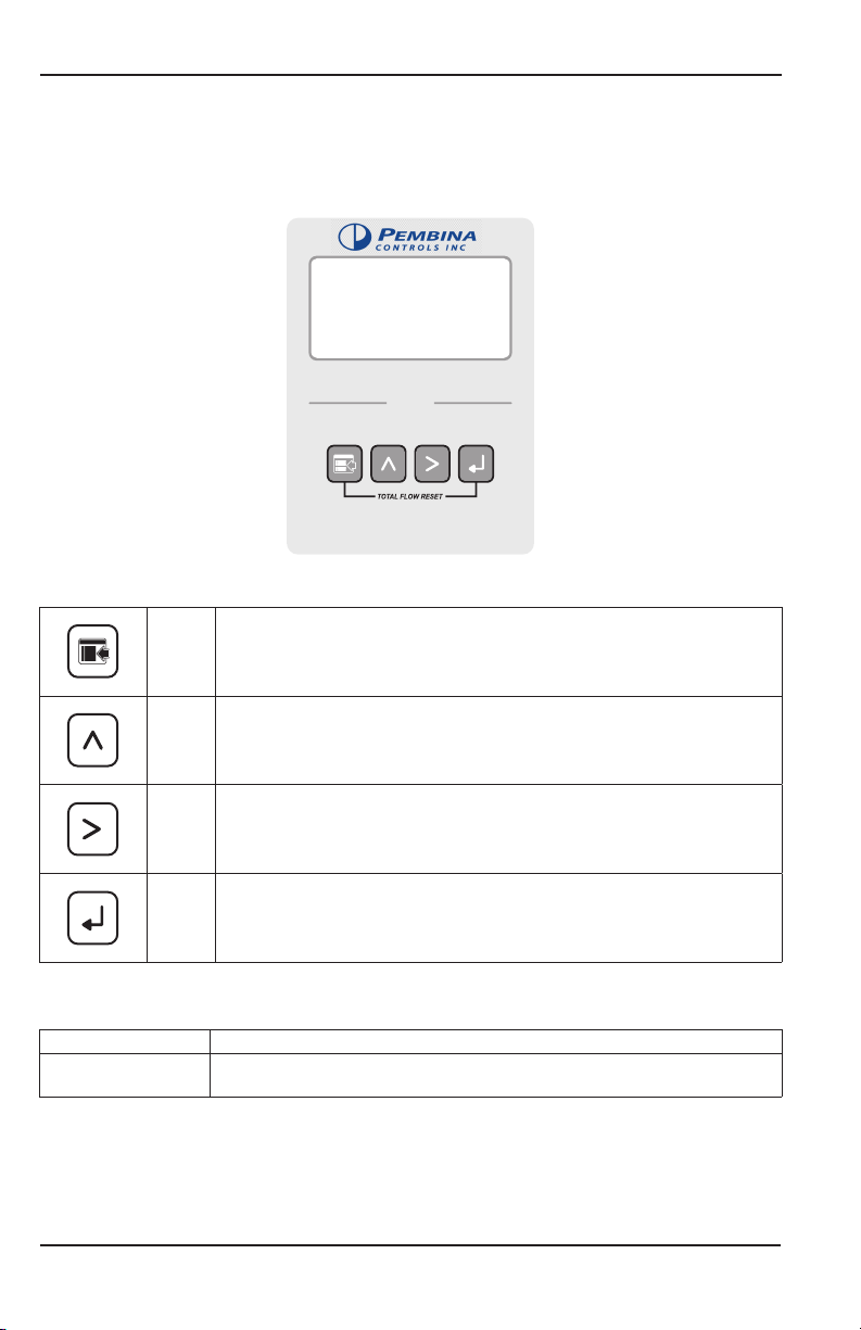
Figure 6: Keypad detail
MENU Switches to Program mode, press and hold for three seconds to enter
Extended Programming mode, and is used in reset process
UP Scrolls forward through the parameter choices, increments numeric variables
and increases display contrast in Run mode
RIGHT Scrolls backward through the parameter choices, moves the active digit to
the right and decreases display contrast in Run mode
ENTER Saves programming information, advances to the next programming
parameter, and is used in the reset process
Special Functions
MENU + ENTER Simultaneously press and hold to reset the current totalizer
UP + RIGHT Simultaneously press and hold to show the firmware version number, then
the grand total
BP2900
Inhaltsverzeichnis
Andere Pembina Messgerät Handbücher


