
Playworld Systems XX3170 Bedienungsanleitung
Installation Instructions
Models XX3170 and XX3170S
ECN2382
Page 1 of 14
Installation Instructions
Playworld Systems®
Models XX3170 and XX3170S
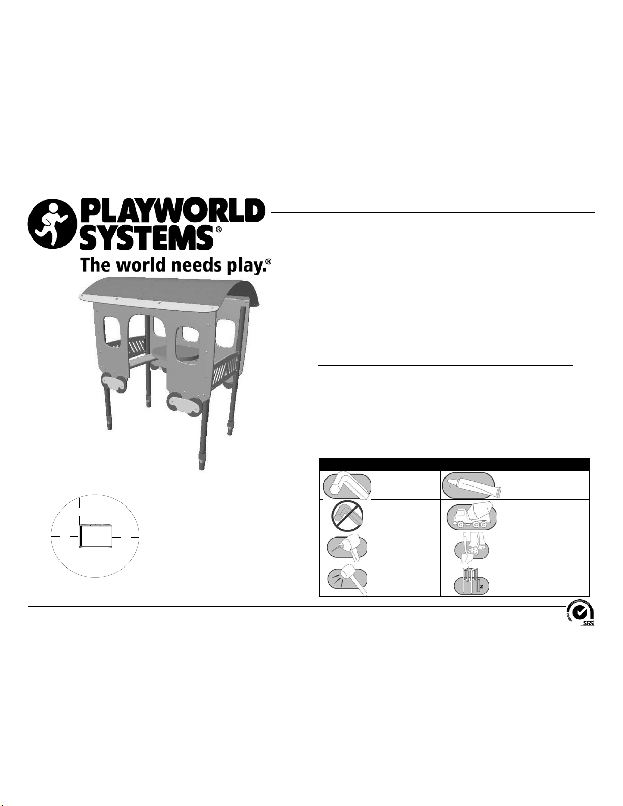
Dining Car
In-Ground and Surface Mount
Installation Preparation
Recommended Crew: ...........................Two (2) adults
Installation Time:...................................5 man-hours (in-ground)
Installation Time:...................................3 man-hours (surface mount)
Concrete Required:...............................0.12 cubic yard (0,09 cubic meters)
Use Zone:..............................................Refer to the information below
User Group Age (years): ....................... ASTM/CSA: 2-12, EN: 2-14
Assembly View (representative model)
ICON KEY
Fully Tighten
Hardware Add 1 Drop of
Thread Locking Adhesive
Do Not Fully Tighten
Hardware Pour Concrete
Drill Dig Footing Holes
Hammer Critical Fall Height
A
A
A
A
Equipment Use Zone
A - (ASTM) 72 in. (1830 mm)
(CSA) 1800 mm
(EN) 1500 mm
Refer to the Elevation View for the specific Critical Fall Height for the component.
Installation Instructions
Models XX3170 and XX3170S
ECN2382
Page 2 of 14
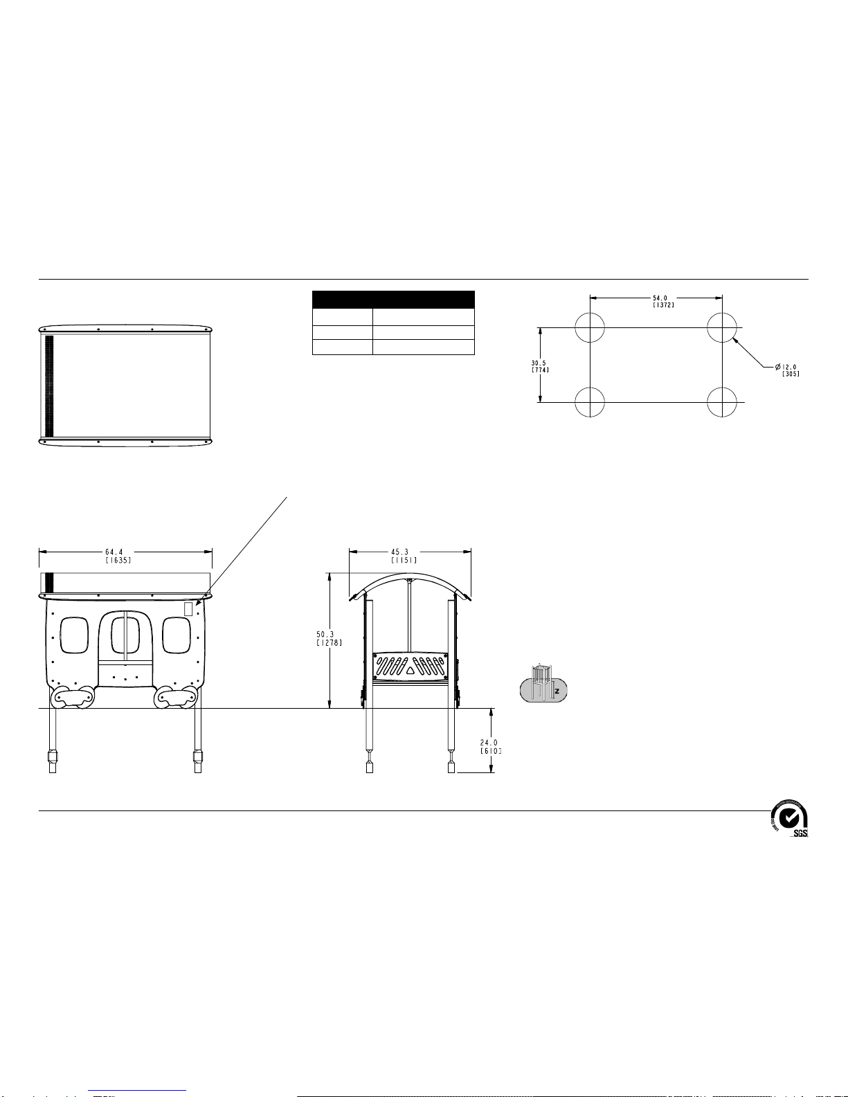
Top View
Elevation Views
XX3170
Footing Diagram
12.6" (320 mm)
KEY
Position Unit of Measurement
Top # Inches
Bottom # [Millimeters]
Apply Surfacing Warning Labels Here
and on Opposite Side
(see Arrows)
Installation Instructions
Models XX3170 and XX3170S
ECN2382
Page 3 of 14
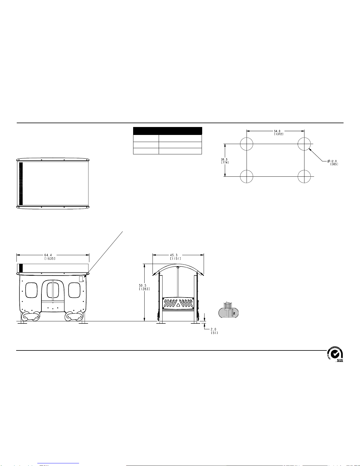
Top View
Elevation Views
XX3170S
Footing Diagram
KEY
Position Unit of Measurement
Top # Inches
Bottom # [Millimeters]
12.6" (320 mm)
Apply Surfacing Warning Labels Here
and on Opposite Side
(see Arrows)
Installation Instructions
Models XX3170 and XX3170S
ECN2382
Page 4 of 14
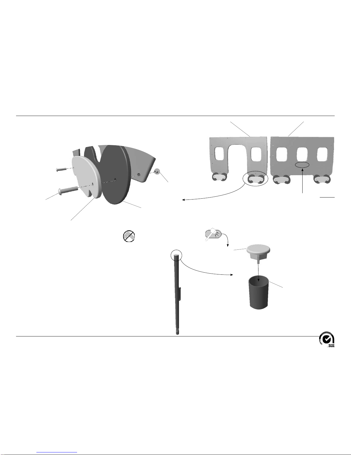
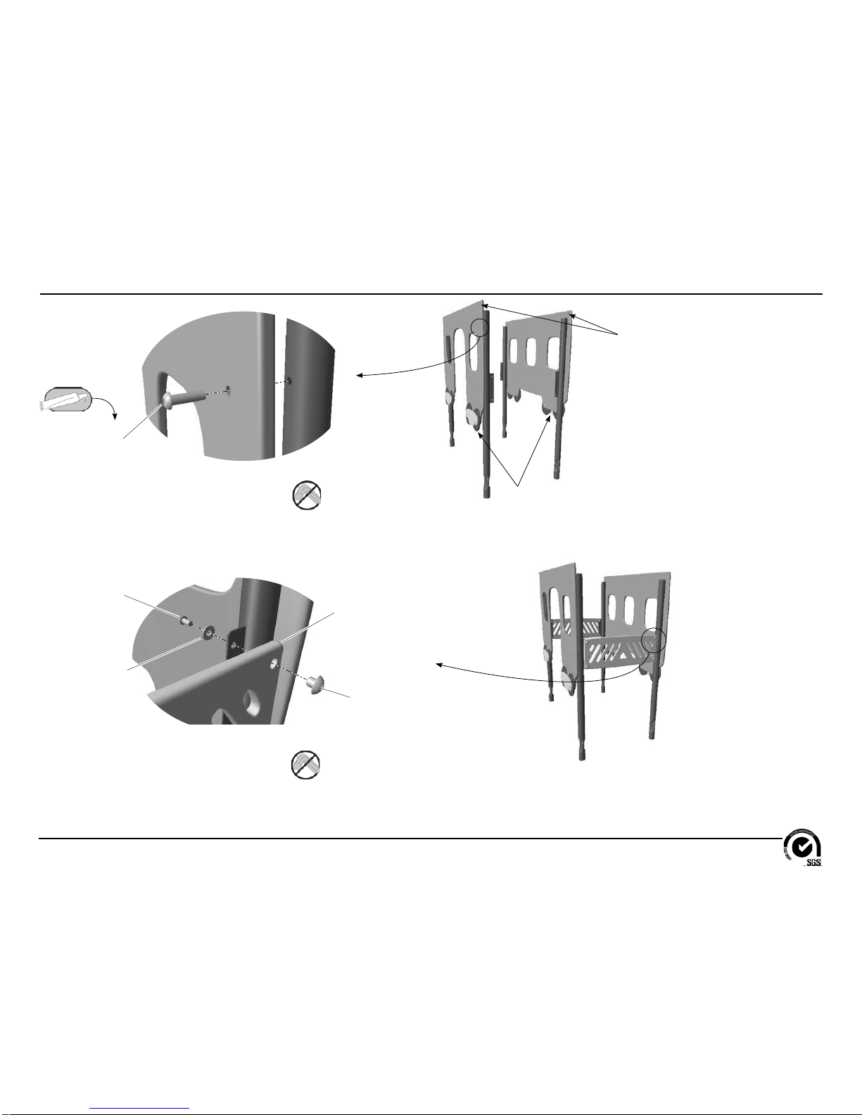
Follow the details in alphabetical order. For clarification, each detail references the
step description. The step descriptions start on page 9. Door Panel
BFC0293
(1 Total)
3/8" x 1-1/2"
Button Head Bolt
BAE06645
(8 Total)
Wheel Cover
BFC0307
(4 Total)
12" Dia. Wheel
BFC0303
(4 Total)
3/8" Button Head Nut
BAE0663
(8 Total)
Window Panel
BFC0294
(1 Total)
Important Note: Place the wheels on the opposite
side of the window panel that has three larger counter
bored holes in the center.
Detail A
Step 4
Attach the wheels to the door and window panels. End Cap
AAU0198
(4 Total)
Support Post
AFM0503 (in-Ground)
AFM0501 (Surface Mount)
(4 Total)
Detail B
Step 5
Insert the end caps into the support posts.
Installation Instructions
Models XX3170 and XX3170S
ECN2382
Page 5 of 14
3/8" x 1-1/4"
Button Head Bolt
BAE0666
(16 Total)
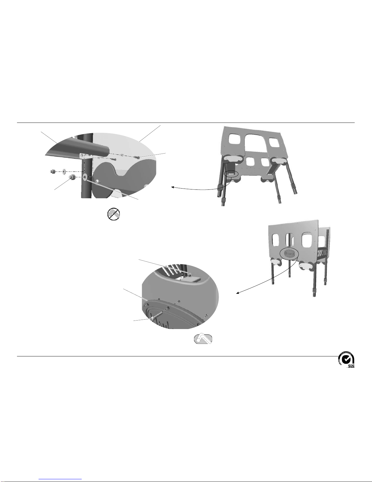
Detail C
Step 6
Attach the panel assemblies to the support posts.
Note: Thesideof the panelswiththe
wheels must be facing out.
Detail D
Step 7
Attach the backrests to the support posts.
Backrest
BFC0292
(2 Total)
3/8" x 3/4"
Button Head Bolt
BAE0659
(8 Total)
1" O.D. Flat Washer
BAE0600
(8 Total) 3/8" Button Head Nut
BAE0663
(8 Total)
Note: Leave the top holes on the panels
open for attachment of the roof.
Installation Instructions
Models XX3170 and XX3170S
ECN2382
Page 6 of 14
Window Panel
Panel is shown
transparent for
ease of viewing
the connections.
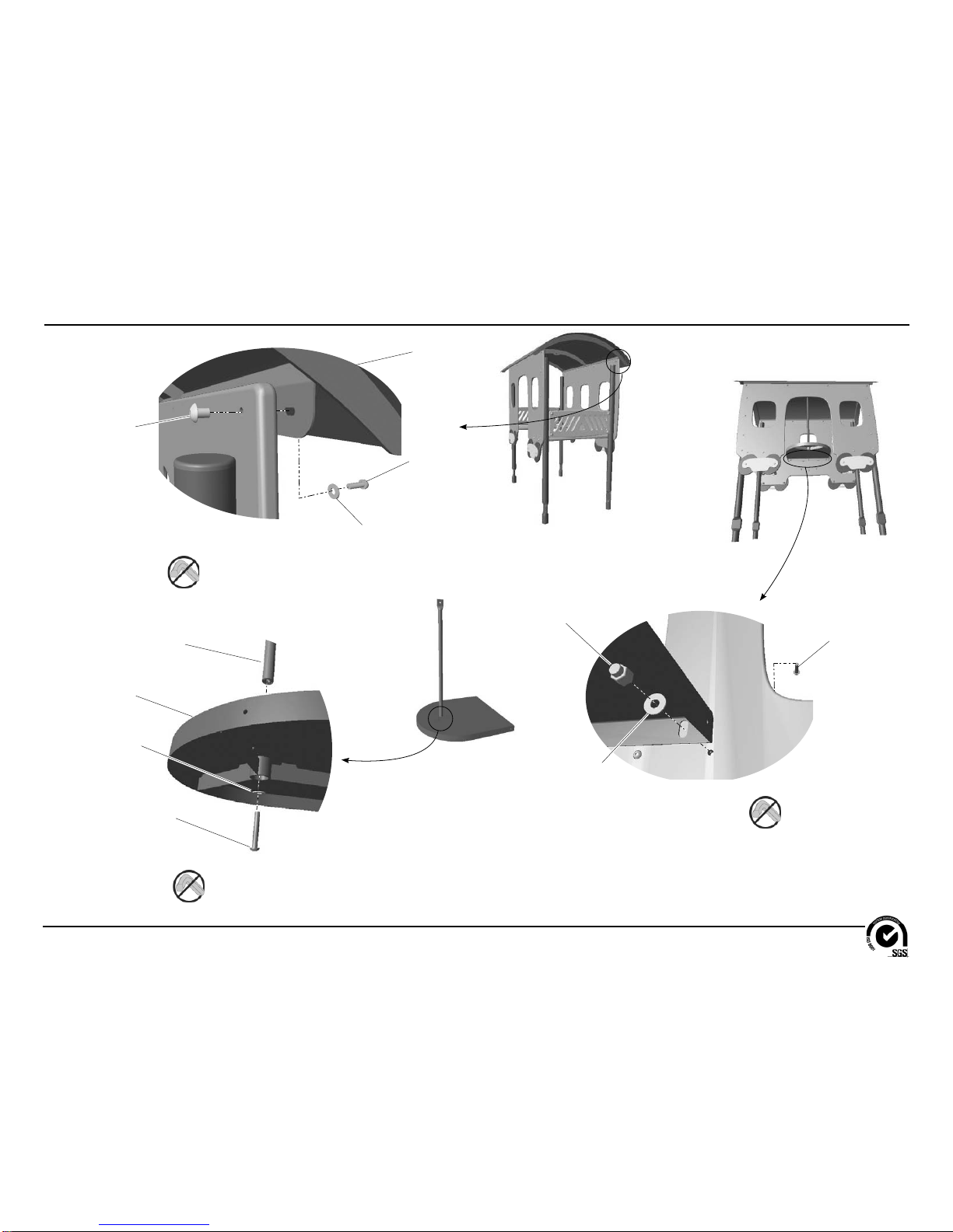
Detail E
Step 8
Attach the seat planks to the panels.
Seat Plank
BPM0258
(2 Total)
3/8" x 1-1/2"
Button Head Bolt
BAE06645
(8 Total)
1" O.D. Flat Washer
BAE0600
(8 Total)
3/8" Lock Nut
BAE0620
(8 Total)
Detail F
Step 9
Attach the logo plate to the window panel.
Logo Plate
BFC0299
(1 Total)
1/4" x 1"
Button Head Bolt
BAE01522
(6 Total)
1/4" Button Head Nut
BAE0161
(6 Total)
Installation Instructions
Models XX3170 and XX3170S
ECN2382
Page 7 of 14
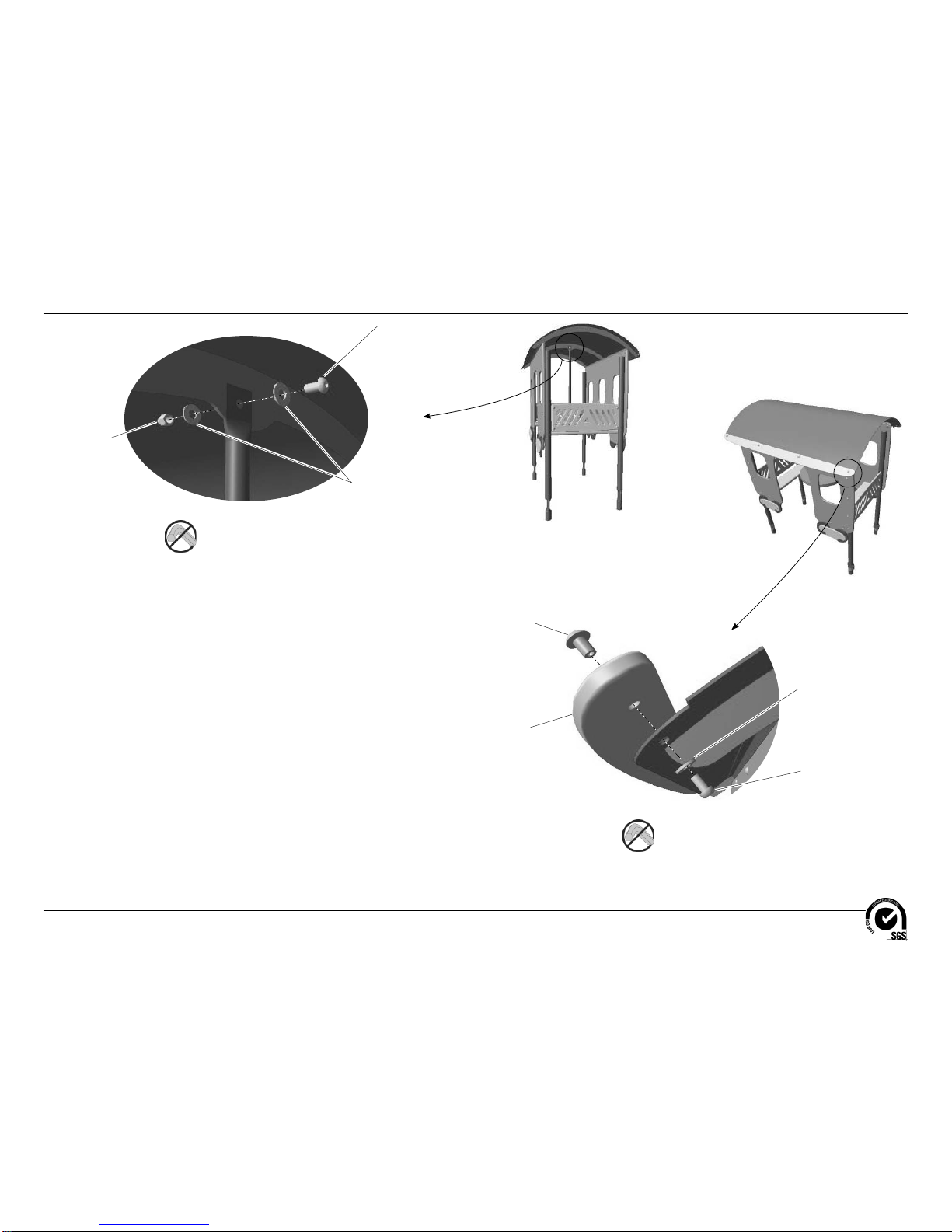
Detail G
Step 10
Attach the roof to the panels.
Roof
AFM0507
(1 Total)
1/4" x 3/4"
Button Head Bolt
BAE01524
(8 Total)
1/4" Button Head Nut
BAE0161
(8 Total)
1/4" Flat Washer
BAE0158
(8 Total)
Detail H
Step 11
Attach the table support to the table.
3/8" x 2-1/2"
Button Head Bolt
BAE0668
(1 Total)
1" O.D. Flat Washer
BAE0600
(1 Total)
Table
BPM0259
(1 Total)
Table Support
AFM0506
(1 Total)
Detail I
Step 12
Attach the table to the window panel.
3/8" x 1-1/2"
Button Head Bolt
BAE06645
(2 Total)
1" O.D. Flat Washer
BAE0600
(2 Total)
3/8" Lock Nut
BAE0620
(2 Total)
Installation Instructions
Models XX3170 and XX3170S
ECN2382
Page 8 of 14
Detail J
Step 13
Attach the table support to the roof.
3/8" x 3/4"
Button Head Bolt
BAE0659
(1 Total)
1" O.D. Flat Washer
BAE0600
(2 Total)
3/8" Lock Nut
BAE0620
(1 Total)
Detail K
Step 14
Attach the roof trim to the roof.
Roof Trim
BFC0295
(2 Total)
1/4" x 1/2"
Button Head Bolt
BAE01521
(8 Total)
1/4" Button Head Nut
BAE0161
(8 Total)
1/4" Flat Washer
BAE0158
(8 Total)
Installation Instructions
Models XX3170 and XX3170S
ECN2382
Page 9 of 14
Notes Before You Begin: Do not over tighten bolts during assembly, only snug
tighten them until assembly is complete.
Carefully read and understand these installation instructions before you
begin.
Step 1: Before attempting to assemble your equipment, please review all
installation information carefully. Should you experience any difficulty during the
installation process, please call us at the phone number shown on the last page
of these instructions.
Step 2: Separate and identify all components and hardware.
Step 3: Excavate, or prepare, the footings as shown in the annex at the end of
this document. Use the Component Footing Details for the in-ground model.
For ease of installation, assemble the component near it's footing.
Step 4:Attach the wheels to the door and window panels. See DetailA. Position
the wheels and wheel covers against the lower sections of the panels and attach
as shown.
Important Note: Place the wheels on the opposite side of the window panel that
has three larger counter bored holes in the center.
Step 5: Insert the end caps into the support posts. See Detail B. Insert the caps
into the open end of the posts and pound in place using a rubber mallet. If a
rubber mallet isn't available, cover the end cap with a piece of wood to protect
the finish.
Step 6: Attach the panel assemblies to the support posts. See Detail C. Place
the support post against each end of both panel assemblies on the opposite side
from the wheels, apply a drop of thread locking adhesive to the bolt threads, and
attach as shown.
Note: Leave the top holes in the panels open for attachment of the roof.
Step 7: Attach the backrests to the support posts. See Detail D. Position each
backrest against the mounting brackets on the support posts and attach as
shown.
Step 8: Attach the seat planks to the panels. See Detail E. Position the seat
planks between the panels and align with the holes over the wheels, and attach
as shown.
Step 9:Attach the logo plate to the window panel. See Detail F. Position the logo
plate over the center of the window panel, align the holes, and attach as shown.
Fully tighten the connections according to tightening torque specifications (See
Final Details).
Step 10:Attach the roof to the panels. See Detail G. Place the roof on top of the
panels and attach as shown.
Step 11:Attach the table support to the table. See Detail H. Position the support
in the hole on top of the table and attach as shown through the bottom of the
table.
Step 12: Attach the table to the window table. See Detail I. Position the table
against the inside middle of the window panel with the table support over the roof
strut and attach as shown.
Step 13: Attach the table support to the roof. See Detail J. Attach as shown.
Step 14:Attach the roof trim to the roof. See Detail K. Position the roof trim over
the top edge of the roof with the rounded sides facing out and attach as shown.
Final Details.
Step 15: With adequate manpower place the assemble component in, or on, it's
footing. Plumb and level the component. Tighten all fasteners. Fully tighten all
fasteners according to tightening torque specifications.
Torque Specifications:
Bolts and nuts - Snug tighten and then tighten an additional one half turn.
In-Ground: Block and brace for concrete. Pour concrete after all equipment has
been assembled. Allow 72 hours for concrete to completely cure.
Surface Mount: Bolt down all surface mount supports in accordance with
specifications provided by your registered structural engineer.
ImportantNote: Surfacemounthardwareisnotsupplied.Customerisresponsible
for concrete base and for providing surface mount hardware as specified by a
registered structural engineer for each specific project application.
Step 16: Apply the Surfacing Warning label to the outside of the Dining Car at
the places designated on Elevation View. Surface must be clean and dry before
applying the label.
Step 17: For areas complying with ASTM standard F1487 or the CSA Z-614,
apply the age appropriate label to the component at eye level.
Installation Instructions
Models XX3170 and XX3170S
ECN2382
Page 10 of 14
Bill of Materials
XX3170 - DINING CAR
PART NO. DESCRIPTION QTY.
AAU0198 CAP - 2-3/8" O.D. x 10 GA. END 4
AFM0503 FAB METAL - 2-3/8" O.D. x 64" 4
AFM0506 FAB METAL - 1.029" O.D. x 31-1/16" WITH INSERT 1
AFM0507 FAB METAL - ROOF ASSEMBLY - DINING CAR 1
BAB0032 LABEL - TAMPER RESISTANT SURFACE WARNING 2
BAD0085 THREAD LOCKING ADHESIVE 1
BAE0158 WASHER - 1/4" S.A.E. FLAT 16
BAE0161 NUT - 1/4"-20 x 7/16" BUTTON NUT 22
BAE0600 WASHER - 1" O.D. FLAT 21
BAE0620 NUT - 3/8"-16 LOCK w/ NYLON CAP 11
BAE0659 BOLT - 3/8"-16 x 3/4" BUTTON HEAD - SS 9
BAE0663 NUT - 3/8"-16 x 7/16" BUTTON HEAD - SS 16
BAE0666 BOLT - 3/8"-16 x 1-1/4" BUTTON HEAD - SS 16
BAE0668 BOLT - 3/8"-16 x 2-1/2" BUTTON HEAD - SS 1
BAE0900 WRENCH - 5/32" SHORT HEX KEY 1
BAE0902 TOOL - 7/32" SHORT HEX KEY WRENCH 1
BAE0922 TOOL - TT 45 L WRENCH 2
BAE01521 BOLT - 1/4"-20 x 1/2" BUTTON HEAD - SS 8
BAE01522 BOLT - 1/4"-20 x 1" BUTTON HEAD - SS 6
BAE01524 BOLT - 1/4"-20 x 3/4" BUTTON HEAD - SS 8
BAE06645 BOLT - 3/8"-16 x 1-1/2" BUTTON HEAD - SS 18
BFC0292 SHEET - BACKREST 2
BFC0293 SHEET - DOOR PANEL 1
BFC0294 SHEET - WINDOW PANEL 1
BFC0295 SHEET - DINING CAR ROOF TRIM 2
BFC0299 SHEET - PLAYEXPRESS LOGO 1
BFC0303 SHEET - 12" DIAMETER WHEEL 4
BFC0307 SHEET - 12" x 5" WHEEL COVER 4
BPM0258 PLANK - 8.00" x 32.76" 2
BPM0259 TABLE - 23.38" x 23.09" x 1.58" 1
ALB0025 LABEL - AGE APPROPRIATE SHEET 1
Dieses Handbuch passt für folgende Modelle
3
Inhaltsverzeichnis


