Pro XK3190-A9+ Bedienungsanleitung

XK3190-A9+
Weighing Indicator
USER’ S MANUAL

X K 3 1 9 0 - A 9+
2
Content
Chapter One Technical Parameter…………………………………………………….3
Chapter Two Installation…………………………………………………………………..5
I. Indicator front and back scheme……………………………………….5
II. Connection between Load cell and Indicator……………………..5
III. Connection between Printer and Indicator…………………………6
IV. Connection between Scoreboard and Indicator………………….7
V. Connection between Serial communication interface and
indicator……………………………………………………………………………..9
Chapter Three Operation…………………………………………………………………….12
I. Start and Start with Auto-zero……………………………………………12
II. Manual zero (semi auto zero)…………………………………………….12
III. Tare
function………………………………………………………………………12
IV. Setting and operation of Date and Time…………………………….13
V. Battery application…………………………………………………………….13
VI. Inner code
display………………………………………………………………13
VII. Saving for Data
record………………………………………………………..14
VIII. Printing
operation………………………………………………………………16
IX. Report
printing…………………………………………………………………..19
X. Delete of Data
record…………………………………………………………20
XI. How to input memorized TARE weight………………………………20
XII. Power saving…………………………………………………………………….21
XIII. Check the software version………………………………………………..21
Chapter Four Maintenance and Cautions……………………………………………21
Chapter Five Information Indication…………………………………………………..23
Appendix……………………………………………………………………………………..…………25
DEAR USERS:
PLEASE READ THIS USER’S MANUAL CAREFULLY BEFORE USING
THE INDICATOR

X K 3 1 9 0 - A 9+
3
Chapter One Technical Parameter
Model XK3190-A9+
Accuracy Class III, n=3000
Conversion Δ-Σ type of A/D
Input signal range -16 mV~ 18 mV
Conversion speed 10 times/second
A/D resolution code 1 million code
Calibration All operation made by keys
Excitation power DC, 5V, able to connect with 8pcs of 350Ω load cells or
16pcs of 700Ωload cells
Load cell connection
method
6 wire method, long wire auto compensation
Display 7 LED digit, 7 status indicating lights, 3 battery
indicating lights.
Display circulation 100ms
Division 1/2/5/10/20/50/100 optional
Clock Can display year/month/day, hour/minute/second,
auto reap year and moth
Number keys 0~9
Function keys 15 (10 of them are share with number keys for
combine application)
Material for keys Light touch type of pellicle
Scoreboard connection
interface
Serial output
Transmission method Current loop/ RS232 signal
Transmission data type 11 bytes
Baud rate 600
Transmission distance ≤30m
Serial communication interface
Transmission method RS232C/RS422(optional)/ RS485(optional)
Baud rate Baud rate option 600/1200/2400/4800/9600

X K 3 1 9 0 - A 9+
4
Transmission data format
10 bytes: 1 byte is start, 8 data bytes (ASC II code), 1
byte is stop.
Transmission distance RS232:≤30m
RS422/RS485:≤1200m
Standard parallel output
interface
To connect with TpuP 16 micro printer; wide line
printer like M800、KX-P1121、KX-P1131、LQ300K
+、LQ1600K; POS58, T58D thermal micro printer.
Built-in printer (for A9+P) Printing system: dot-matrix (96 dots each line), adopts
M-150 II printing head or TpuP-16B printing head.
Printing paper: standard blank paper, width:
44.5±0.5mm, thickness: 0.07mm, paper roll external
diameter less then 50mm
Life span for Printing head: 0.5×10⁶ lines
Printing ribbon: blue ribbon are installed in the
removable ribbon box, its life span is 1×10⁶ lines
Data saving 1000 units of truck No. and tare, 201 unit of cargo,
1001 unit of weighing record
AC power AC 220V(-15%~+10%);50Hz(-2%~+2%)
DC power Adopts 6V/10AH battery (external)
Battery application About 24h (fully charge without using the built-in
printer)
Battery charging About 30h
AC fuse 500mA
Application temperature 0℃ -- 40℃
Storage temperature -25℃ -- 55℃
Relative humidity ≤85%RH
Pre-heat time 15 min
Appearance 310×195×186 (mm)
Weight About 2.5kg

X K 3 1 9 0 - A 9+
5
Chapter Two Installation
I. Indicator front and back scheme
(Graph 2-1) Front View
(Graph 2-2) Back View
II. Connection between Load cell and Indicator
1. The 9-pin socket is used for connection with load cell, which foot definition is

X K 3 1 9 0 - A 9+
6
shown in graph 2-3.
2. If 4-core shielded cable is used, +S must be short connected with +E, so did -S and
-E.
3. ▲!Indicator must be reliably connecting to Load cell and shielded-cable of load
cell must be reliably connected to underground. If indicator is powered on,
the user should not plug or unplug in order to protect the indicator and load
cell.
4. ▲!Load cell and indicator are static sensitive devices; you must adopt anti-static
measures. In order to protect the operator, indicator, and relevant devices,
you should install lightning rod in the thunderstorm frequently happening
area
Graph 2-3: Connection of the load cell
III. Connection between Printer and Indicator
1. The printing interface adopts the standard parallel interface. The 25-pin RS232
socket is illustrated below:
5 Shield
8 -IN
9 +IN
1 -E
2 -S
7 +S
6 +E +
_
Terminal of Indicator Terminal of Sensor
Bridge of Power Supply
Signal Output
12 3 4 5
6789
-E -S Shield
+E +S -IN +IN

X K 3 1 9 0 - A 9+
7
2. Caution for Printing
▲!Printing function must be set in indicator before using it.
▲!Printer and Indicator’s interface must be connected by professional printer
connection wire. If the connection of each foot is wrong, it will damage indicator’s
output interface or printer’s input interface, or worse will be damage of indicator or
printer.
▲!When you use printer, you must make sure each pin of the interface is correctly
connected, then turn on the indicator, and turn on the printer at last. When you stop
using the printer, you must turn off the printer first, then off the power of indicator,
and then disconnect the wires. If the order is wrong, it may damage the indicator and
printer. Please NOTICE THAT!
▲!Due to the various type of printer exists in the market which has different
function and capability, please use the printer with the model which we recommended.
▲!Printer must connect with GND reliably. Otherwise, it may interfere the normal
function of indicator or damage the indicator and printer.
IV. Connection between Scoreboard and Indicator
▲!Interface of indicator for scoreboard’s and scoreboard’s connection must be
correct, if there is any mistake on that, it will damager the indicator interface and
scoreboard’s input interface, or even worse, the indicator and scoreboard will be
damaged. The wire for connection must be assorted professional connection wire.
1. Scoreboard adopts 15 core RS232 socket (share with serial communication interface),
the definition of foot 9 and 10 is as follow graph (2-5).

X K 3 1 9 0 - A 9+
8
(Graph 2-5 ) serial communication and scoreboard output interface
2. Scoreboard adopts current loop or RS232 by ACII code serial output, baud rate is 600.
Each frame has 11 bytes of data, 1 start bit (0), 8 data bit (lower bit is in the front), 1 stop
bit (1).
3. Every unit of data is send out in every 100ms, each unit of data contains 3 frames data,
its definition is as follow (2-6):
First frame:
(Graph 2-6.1) first frame wave graph
Second frame:
(Graph 2-6.2) second frame wave graph
Third frame:
(Graph 2-6.3 ) third frame wave graph

X K 3 1 9 0 - A 9+
9
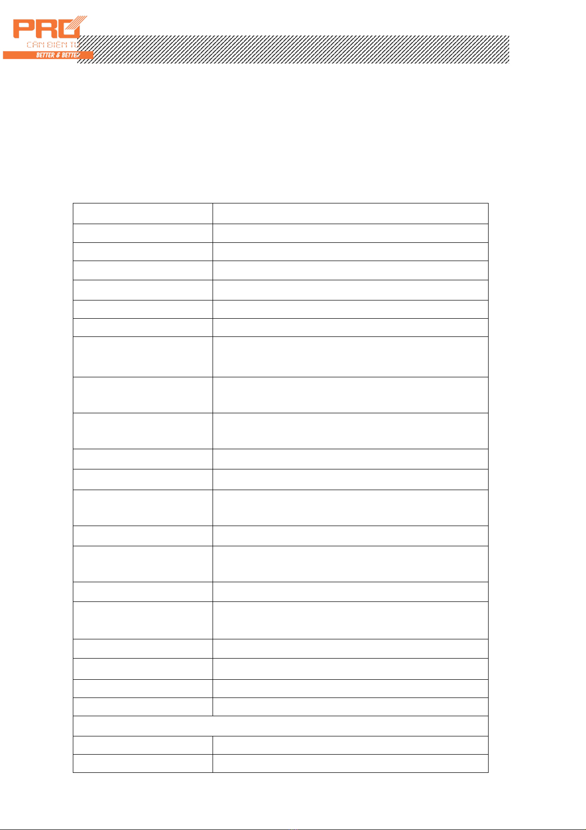
First frame data:mark bit is 0
X : D0、D1、D2 – is the location of decimal ( 0~4 )
Y : D3 — is weight symbol ( 1-negative、0-positive )
D4 — back up
G 18~G16: Weight (N.W.) data
Second frame:mark bit is 0
G15~G8: Weight (N.W.) data
Third frame:mark bit is 1
G7~G0 : Weight data
G0~G18:19 digits ACII code of weight (N.W.) consist by the digits from low to high
V. Connection between Serial communication interface and indicator
▲!communication interface output line should connect with computer correctly, if
there is any mistake on that, it will damage indicator output interface or computer
communication input interface or even damage indicator and computer and its
external devices.
▲!For computer communication, it requires knowing computer technology and
programming ability. Unprofessional people, please don’t connect it at your will.
XK3190-A9+ has RS232/RS422 (optional)/RS485 (optional) serial communication
interface, can communicate with computer.
1. Communication interface adopts 15-core RS232 socket (share with scoreboard), its
definition of foot is shown in Graph 2-5 (foot 6.7,8) RS232 or foot 1, 2, 3, 4, 8
(RS422/RS485)
2. All data is of ASCII, every unit of data consist of 10 bytes, first bit is start bit, 10th
bit is stop bit, 8 bit in the middle is data bit, communication method divided as
follow:
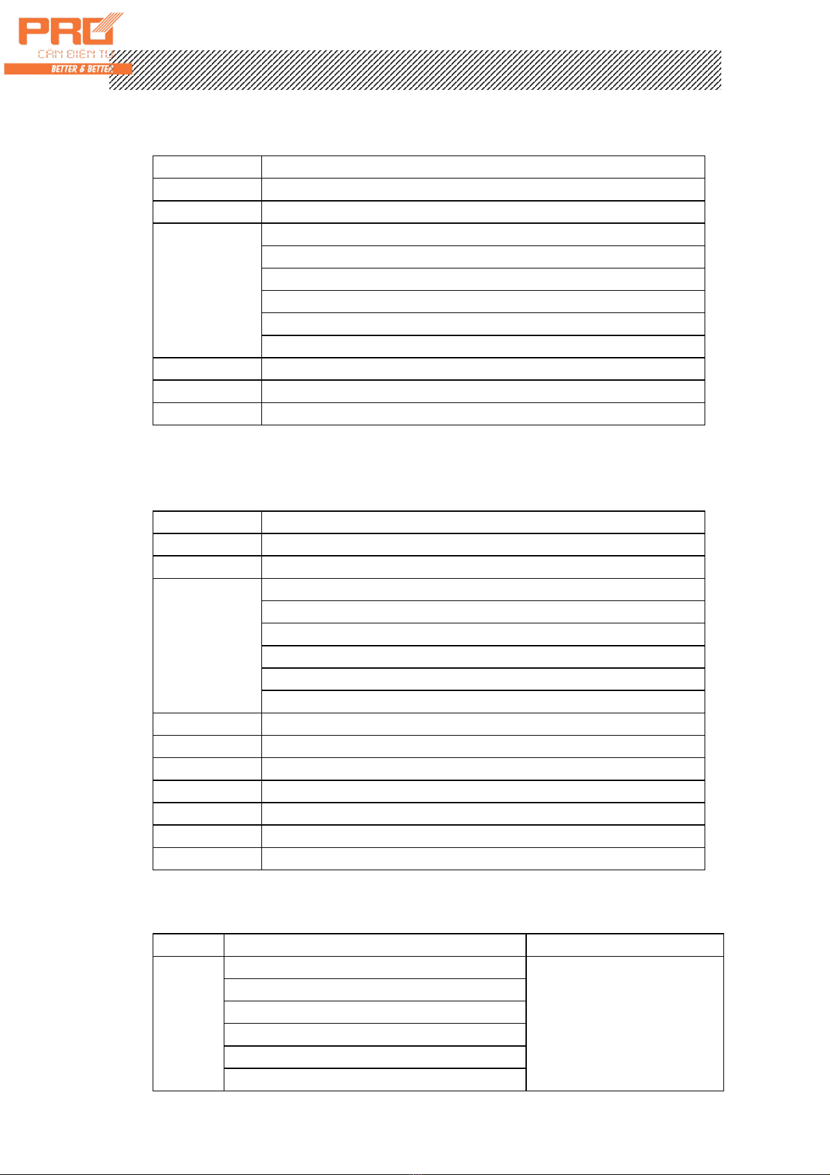
(1) Continuous method (Tf=0):
The sending data is the current weight (G.W or N.W). each frame of data
consist of 12 unit of data. Format as follow:
X
th
bit Content and note
1 02(XON) start
2 + or - symbol bit
3 Weighing data high bit
: Weighing data :
: Weighing data :
8 Weighing data low bit
9 Decimal No. from right to left(0~4)
X
th
bit Content and note
10 XOR checking 4 bit in high bit
11 XOR checking 4 bit in low bit
12 03(XOFF) end
XOR=2 3 ……8 9⊕ ⊕ ⊕
(2). Order method (tF=1):

X K 3 1 9 0 - A 9+
10
Indicator output corresponding data according to upper monitor’s order. Each
order each frame of data. Upper monitor sending order as follow:
X
th
bit Content and note
1 02(XON) start
2 A~Z address S/N
3
A~F order A:handclasp
order B:read G.W.
Order C:read TARE
Order D:read N.W
Order E:read truck No.
Order F:read cargo No.
4 XOR checking 4 bits of high bit
5 XOR checking 4 bits of high bit
6 03(XOFF) end
XOR=2 3⊕
Indicator output content:
X
th
bit Content and note
1 02(XON) start
2 A~Z address S/N
3
A~F Order A:handclasp
Order B:send G.W.
Order C:send TARE
Order D:send N.W
Order E:send truck No.
Order F:send cargo No.
4 Output corresponding data according to order
: Output corresponding data according to order
n-1 Output corresponding data according to order
n Output corresponding data according to order
n+1 XOR checking 4 bits of high bit
n+2 XOR checking 4 bits of low bit
n+3 03(XOFF)
XOR=2 3 ……⊕ ⊕ ( n-1 ) n⊕
Indicator output 4~n data content as follow:
Order A
No Data 6 units of data for each
frame
Order B
G.W,format: 14 units of data for each
frame
a: symbol (+ or -)
b: G.W. ( 6 bits)
: (from high to low)
g
h: decimal from right to left ( 0~4)
Inhaltsverzeichnis
Andere Pro Messgerät Handbücher

Pro
Pro OFT-3 Bedienungsanleitung

Pro
Pro AQ180G Bedienungsanleitung

Pro
Pro LK-360.3DG Bedienungsanleitung

Pro
Pro DP1008 Series Bedienungsanleitung

Pro
Pro PM-100 Series Bedienungsanleitung

Pro
Pro PRO-EP003 Bedienungsanleitung

Pro
Pro PM-501X-VFL Bedienungsanleitung

Pro
Pro TM1018 Bedienungsanleitung

Pro
Pro OCC-CWDM-301-18B Bedienungsanleitung


