
Progres AgroBee-L Bedienungsanleitung
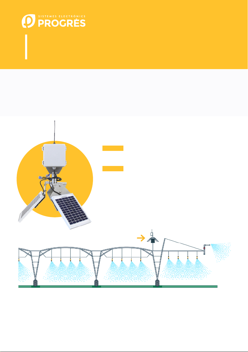
AgroBee-L GNSS System
AgroBee-L Manual
The GNSS (Global Navigation Satellite System) is a very low consumption radio module
that is part of the AgroBee-L radio system, and that integrates a GPS-GLONASS receiver
inside it to determine the geographical position of the module in question. It also allows
the activation of latch solenoids and the reading of digital and analog sensors.
The AgroBee-L GNSS model oers the following:
Option 1
• Determination of geographic position
Option 2
• Determination of geographic position
• 2 2-wire or 3-wire latch solenoids
• 1 counter or digital input or rain gauge
• 2 4 -20mA analog sensors
The AgroBee-L GNSS module is designed to be installed on top of a post on the last tower of
the pivot, be it circular or linear. Consequently, the module allows us to locate the geographical
position of the pivot on a map and its direction of movement.
AgroBee-L GNSS

2· User’s manual | AgroBee-L
Technical characteristics
Power supply: GNSS:
Solar: 3 x 5W → 3,6V Panels plus 4000 mAh Ni-MH battery
Energy consumption: GNSS Average consumption:
90 mW
CAUTION! When handling the
battery pack, take the following
precautions: do not short-circuit,
disassemble, or deform it, do not heat
or burn it, and do not place the
battery pack near any open flame.
Power supply
When configuring an AgroBee-L GNSS module, you must enter the geographical coordinates
of the centre point of the pivot and of the starting or reference point 0°, if it is circular, as para-
meters.
If the pivot is linear, the centre point will be the le end, and the starting point will be the right
end. These coordinates are given in degrees, minutes, and seconds, and can be entered through
the Module Reader or the Agrónic to which said module is linked.
Through the parameters entered and once the module has determined its geographical
position, this GNSS module can provide us with the following values:
• Measures delivered:
‒ Angle with respect to the
starting or reference point of 0°
(clockwise)
‒ Angle respect to the initial point
or reference point of 0° (counter-
clockwise)
‒ Distance from the centre point
‒ Angle of the reference point 0°
with respect to geographic North
The AgroBee-L GNSS module has a 4 Ah internal battery and three 5 W solar panels that are
delivered along with the module.
This module is always active and collects data from the satellites it has in view. This allows it be
precise when pinpointing its position, the maximum that the system allows, about +/- 3 metres.
The navigation system’s antenna is integrated inside the module.
Option 1 (GNSS function only) does not present any kind of wiring, so, in this case, it is not
necessary to make any connections.
In Option 2, the wiring is logically necessary, since there are connections for the latch solenoids
and analog and digital sensors.

User’s manual | AgroBee-L · 3
Number 2
Type 5 Vdc or 12 Vdc (Analog
sensor power supply)
Maximum current: 50 mA
Number 2
Type 6 Vdc, 9 Vdc, 12 Vdc, 19
Vdc Trigger time: 80 ms
Capacitor charge: 4700 µF
Outputs
Maximum distance betweeen sensor and
AgroBee-L: 50m
Number 1
Type For potential-free contacts
Number 2
Type Analog (12 bits)
Inputs
Temperature -10 °C a +60 °C
Moisture < 95 %
Altitude 2000 m
Pollution Grade II
Environment
Height 460 mm
Width 295 mm
Depth 590 mm
Weight (approx.) 3,35 Kg
Box dimensions GNSS
This symbol indicates that electrical and electronic controller must not be disposed of along
with household waste at the end of its useful life. The product must be taken to the correspon-
ding collection point for the recycling and proper treatment of electrical and electronic contro-
ller in accordance with national legislation.
This system conforms with the regulations and other
regulatory documents in the following list:
Electrical
safety
UNE EN 60950-1:2007+ CORR:2007 Information technology controller.
Safety. Part I: General requirements
UNE EN 60215:1995 + A2:1995 Safety requirements for
radiotransmission controller
EMC
ETSI EN 301 489-17 v1.3.2 based on ETSI EN 301 489-1 v.1.7.1:
UNE-EN 55016-2-3:2007 Radiated radio frequency
emissions (30-1000MHz). Class B
UNE-EN 61000-4-2:1997
+ A1:1999 + A2:2001 Electrostatic discharge
UNE-EN 61000-4-3:2007 + A1:2008 Electromagnetic field immunity
UNE-EN 61000-4-4:2005 Transient/burst immunity
UNE-EN 61000-4-6:2008 Current injection: 150KHz-80MHz
Radio
spectrum
protection
ETSI EN 300 328 v1.7.1
(Decision ERC/DEC/(01)07
and Recommendation
CEPT ERC/REC 70-03)
Spurious issuer emissions Coordinator
and Module GNSS. Eective
radiated power Coordinator and
Module GNSS. Frequency dri
Coordinator and Module GNSS.
Declaration of conformity

4· User’s manual | AgroBee-L
The AgroBee-L radio modules are used for the activation of valves and other irrigation elements,
as well as the reading of sensors and meters. It is very low consumption and follows the LoRa
radio modulation, which operates in the 868MHz, 433 MHz and 915 MHz, free bands, obtaining
radio coverage of up to 2500 m between two points (depending on the orography).
AgroBee-L System Operation
Currently, they can be incorporated
into the Agrónic 2500, Agrónic 5500 and
Agrónic Bit Con fertirrigation controllers.
The AgroBee-L system consists of
a coordinator device (located in the
Agrónic 2500, Agrónic 5500 or Agrónic Bit
Con controllers) and by field elements
with dierent functions, depending
on the model in question. This system
does not include the use of repeater
elements, so all modules must connect
directly with their coordinator. The field
modules manage their consumption by
activating the communication in the
precise time of the exchange; the rest of
the time, they are asleep or attending to
irrigation control.
Its low consumption allows it to operate with a solar panel integrated into the module and
supercapacitors or battery (depending on the model). The solar panel stores the energy in the
supercapacitors/battery, oering a long operational life. It is only necessary to replace batteries
in models that include batteries instead of supercapacitors.
The maximum number of modules that an Agrónic controller can manage is 20 units in standard
mode, which can be configured as modules of any of the available types. There is also a priority
mode, which makes it possible for the modules to communicate more oen: in this case, the
number of modules (10) is halved.
To use AgroBee-L modules, it is necessary to assign their outputs to the sectors or generals of
the controller in question, and their inputs to the digital, analog, or counters sensors.

User’s manual | AgroBee-L · 5
Installation
For the supply of radio controller, it is essential to
have a coverage study. This study verifies the viability
of the system according to the profile of the terrain, the
location of the points to be controlled, and the distance
between them. The study is delivered along with the
controller oer.
AgroBee 868 MHz
ESTUDIO DE COBERTURA RADIO
SISTEMES ELECTRÒNICS PROGRÉS, S.A.
El resultado del estudio es
VIABLE
Referencia FINCA RIO GRANDE
Número de estudio
2017 - 001
Instalador AGUAS DEL NORTE
Fecha de creación
05/12/2017
Distribución
instalación
Indicaciones para su correcta instalación
Coordinador altura mínima 6m - cable subministrado 10 m
Otros módulos altura mínima 4.5m - cable subministrado 10 m
Módulo Repetidor altura mínima 6m - sin cable
Garantizar visión directa entre antenas
Comunicación indirecta del coordinador a los módulos, comunicación mediante repetidor
Coordenadas Módulos RPT-EXTERNO 38°50’42.57”N - 6°19’4.14”O
Altura
Visibilidad
Distribución directa entre antenas
The AgroBee-L system has the following features, among others:
• Operation in 868 MHz, 433 MHz and 915 MHz free bands.
• Availability of 13 communication channels plus 18 transmission modes, which allow for the
operation of more than one network in the same area working on the same channel.
• Availability of network code, which allows for filtering the information of several networks
configured with the same parameters.
• Self-adjustable communication rate according to the chosen transmission mode and the
timing mode:
‒ Timing in standard mode (60 –200”). Up to 20 modules.
‒ Timing in priority mode (30 –100”). Up to 10 modules.
• Distances of up to 2500 metres between any module and its coordinator (depending on the
orography).
• Manual actions, consultations, and configuration of the network number, channel,
transmission mode, and communication timing (standard/priority):
‒ In-situ: Through the Module Reader
‒ From a distance: Through the Agrónic
• Battery/charge level reading and solar panel (if any).
• Reading SNR level (signal-to-noise ratio) reception in the module and coordinator (in [%]).
• Reading the status of the last 16 communications and remaining time indicator until the
next communication.

6· User’s manual | AgroBee-L
MODULE INSTALLATION
3 5W
Solar panels
Support for
solar panels
AgroBee-L
GNSS Module
4 3M connectors
Screw the three solar panels
onto the panel support.
Connect the module’s
cables with those of
the panels as shown
in the figure.
IMPORTANT
Do not strip the tips
of the cables.
Place the module on top of
the support and screw it in.
1
3
2
Included material:

User’s manual | AgroBee-L · 7
The AgroBee-L GNSS module incorporates the GPS-GLONASS receiver inside it. For the correct
operation of the system and for greater precision provided by the module when determining the
geographical position, it is very important that the antenna installed in the module is as perpen-
dicular as possible to the ground.
LOCATION SENSORS
To set the cables in the connectors,
press on the blue part with pliers.
Place the whole assembly on top of
a post.
4 5
The GNSS modules have the antenna integrated into the module and in its upper part,
in order to avoid that the structure of the center does not adversely aect the perfor-
mance of the communications.
6
For the correct operation of the system and to have good radio communication, it is very
important that the GNSS module be installed on the last tower and at least 2 meters above
the Pivot metal structure. With this, a correct position reading and communication between
the GNSS module and the Coordinator are achieved.
IMPORTANT
In the event that the Pivot has sprinklers
installed directly on top of the main
pipe, the installation height of the GNSS
module must be increased enough so
that the module does not receive direct
water from the spray.

8· User’s manual | AgroBee-L
Inputs and Outputs
The trigger voltage of the solenoids (digital/latch outputs) is programmable through the Reader
or from the Agrónic, which may be 6, 9, 12 or 19 Vdc. The default voltage is 12 Vdc.
You can also choose the action that a GNSS module will perform with the digital outputs if the
communication is lost. The options are:
• Do not perform any action
• Deactivate all outputs immediately aer losing communication
• Deactivate all outputs aer about 15 minutes aer losing communication.
The GNSS model can work with two- and three-wire latch solenoids:
• 2/3 wire latch solenoids: these modules can drive up to 2 solenoids. The solenoids must be
connected as defined in the wiring table in the next section.
‘Option 1’ of said module does not include the possibility of having inputs and outputs.
‘Option 2’ includes digital outputs, digital inputs, and 4-20mA analog inputs.
DIGITAL OUTPUTS
There is 1 digital input in an AgroBee-L GNSS module, which can function either as a digital
input or a counter/rain gauge input. When the input is connected to a counter, the minimum time
between pulses must be 0.1 seconds and an anti-bounce filter may be enabled in order to avoid
accumulating undesired pulses. Maximum allowed distance between AgroBee-L module and a
digital sensor or meter is 50m.
The said input’s connection must be set according to the following section.
DIGITAL INPUTS
The module in question has up to 2 analog inputs for reading 2 4-20mA sensors. The sensors
must be connected as defined in the table in the next section.
IMPORTANT
To obtain the reading of an analog sensor through a specific “analog input” (1 or 2), the sensor
must be powered by the corresponding “sensor feed” (1 or 2). Therefore, the power supply will be
independent for each sensor.
ANALOG INPUTS

User’s manual | AgroBee-L · 9
To ensure the that the module’s
cable connections are watertight, it
is recommended to use watertight
terminals. The connection through
these terminals must be made
without stripping the cable’s wires.
AgroBee-L
GNSS
Module
Watertight
connection
terminals
Solenoid
‘Option 2’ of the GNSS model is provided with a 7-metre cable hose that allows dierent con-
nections to be made more easily without the need to access the interior of the module:
• GNSS - 12-wire tube
The cables of the dierent tubes will be identified by colours and numbers. Connect them
according to the following table and according to their functionality.
CONNECTION
GNSS (option 2)
Wire colour Function 1
(latch 2 hilos)
Function 2
(latch 3 hilos)
White R1
Brown R2
Green Common (CR-2F) Common Stop (CP)
Yellow - Common Activate (CM)
Grey Digital Input 1 (D1)
Pink Common Digital Input 1 (CD)
Blue Analog input sensor 1 (A1)
Red Common Power Sensors (CA1)
Black Power supply sensor 1 (+V1)
Purple Analog input sensor 2 (A2)
Grey-pink Common Power Sensors (CA2)
Red-blue Power supply sensor 2 (+V2)

10 · User’s manual | AgroBee-L
Settings
For any AgroBee-L module to enter the correct operating mode, you must have an Agrónic
controller (Agrónic 2500, Agrónic 5500 and Agrónic Bit Con) with the AgroBee-L option installed,
which includes the internal coordinator and an antenna with 10 metres of cable. This can be
verified by doing the following in the controller:
Consult Communication AgroBee-L Status: Correct
In the same way, a module must be configured to
communicate with the Agrónic with which you want to
associate it. To do this (if the module is not already confi-
gured at the factory) you must use the Module Reader (or
Agronic Radio Reader, LAR) consisting of a screen and four
keys, that is connected to the AgroBee-L module through
the only connector visible on the inside.
A wireless module reader is also available that allows you
to perform functions without the need for a cable. Consult
the wireless AgroBee Reader manual to learn about the
steps to link it to the controller.
Press the key to enter the main menu. Use the and keys to change the options
within the menu. Use the key to enter the selected menu option. Use the key to return
to the previous hierarchy’s menu.
You will see the following options in the main menu:
• Consult controller
• Consult communications
• Consult digital output
• Consult digital and analog inputs
• Communication parameters
• Input-Output parameters
• Output manual
• Sectors manual
• Various parameters
Once the AgroBee-L module is linked with an Agrónic, all the consultations and
parameters are accessible through the Agrónic.
NOTE
+
-
cc
Andere Handbücher für AgroBee-L
1
Inhaltsverzeichnis


