QMI TRIPLEX Bedienungsanleitung

TRIPLEX™ OIL MIST
MONITORING
SYSTEM
Atmospheric Oil Mist Detection
System Manual
TM4 / AUGUST 2018

QMI TRIPLEX™
Atmospheric Oil Mist Detection System Manual
TM4 / AUGUST 2018
You have chosen a QMI oil mist detection system that has been providing a fast
response without false alarms to protect lives and prevent fires since the early
eighties.
The QMI TRIPLEX™ Atmospheric Oil Mist Detection Systems can locate a hazardous
build up of oil mist in confined areas such as: pump rooms, bow thrusters, purifier
rooms, hydraulic pack areas, and test cells.
We can provide QMI MULTIPLEX™ Atmospheric and Engine Oil Mist Detection
Systems. The MULTIPLEX™ systems have up to 12 channels and can be used to
monitor engine condition continuously to see when and where repairs are needed
thus avoiding unnecessary engine wear and the resulting danger. The MULTIPLEX™
can also be used for larger Atmospheric Systems. For more information please see
our website: www.oilmist.com
© 2018 Quality Monitoring Instruments Ltd.
Errors and omissions excepted. As we strive to improve our service and products specifications may
change or vary.
Type Approval from:
Atmospheric Oil Mist Detection System
TM4 / AUGUST 2018

Table of Contents
Technical Specifications Sheet-4
QMI TRIPLEX Central Monitor Unit (CMU) (Q01T): Photograph and Features Sheet-5
Dimensions of TRIPLEX Monitor Sheet-6
Description of Triplex Monitor (Q01T) Sheet-7
Description of Q10 Atmospheric Sensor Sheet-8
Photograph of Q10 Atmospheric Sensor Sheet-9
Drawing of Q10 Atmospheric Sensor Sheet-10
Positioning and Location of Atmospheric Sensors Sheet-11
Positioning of Q10 Atmospheric Sensor Sheet-12
Schematic of Positioning of Sensors and Best Practice Sheet-14
Fault Alarm and Cable Specification Sheet-16
Wiring Description Sheet-17
Wiring of Socket Sheet-18
Wiring for System Layout Sheet-19
Photograph of Power Supply Board (Q01T05) Sheet-20
Drawing of PSB Sheet-21
Schematic of layout for Wiring Option 1: for 1 to 3 Atmospheric Sensors Sheet-22
Drawing – Connection from Atmospheric Sensor to Monitor Sheet-23
Drawing – Wiring from Atmospheric Sensor to Monitor Sheet-24
Schematic of layout for Wiring Option 2: For 2 or 3 Atmospheric Sensors using a Junction
Box Sheet-25
Photograph of unboxed 3 – Way PCB (Q01T06) Sheet-26
Drawing – Unboxed 3 – Way PCB for a Junction Box Sheet-27
Drawing – Wiring from Monitor to PCB (Q01T06) Sheet-28
Drawing – Connections from PCB to Atmospheric Sensors Sheet-29
Drawing – Wiring from Junction Box PCB to Atmospheric Sensors Sheet-30
Alarm Outputs and Alarm Levels Sheet-31
Graph to show relationship between Oil Mist concentration and Digital Alarm readout Sheet-32
QMI Triplex 4-20mA Analogue Data Output - (Optional) Sheet-33
Operation of Alarm Relays Sheet-34
Alarm Level, Checking And Changing Sheet-35
Test Sequence Sheet-36
Channel Numbers, Changing Sheet-37
To Isolate or Restore a Channel Sheet-38
Restore Alarms Sheet-39
Drawing – Layout of Transistors and Fuses Sheet-41
Fault Directory Sheet-42
Maintenance Procedures Sheet-44
Lens Cleaning Procedure Sheet-45
Suggested Maintenance Plan for Atmospheric Sensors Sheet-46
Replacing Fan (Q1004) in Sensor Sheet-47
Maintenance Kit Check List Sheet-48
Spares, Codes and Descriptions Sheet-49
Returns Procedure Sheet-50
QMI Request For After Sales Information Sheet-51

Atmospheric Oil Mist Detection System
TM4 / AUGUST 2018
EMAIL [email protected] WEBSITE www.oilmist.com 4 East Barnet Road, London, England, EN4 8RW TEL +44 (0)20 7328 3121
Sheet-4
TECHNICAL SPECIFICATIONS
POWER SUPPLY Nominally 110 - 240 VAC 50/60 Hz
MAXIMUM POWER CONSUMPTION 100W
MAXIMUM SAMPLING CHANNELS 3
CYCLE TIME 500 milliseconds simultaneously on all
channels
MEASURING SYSTEM Time multiplex analogue signal
SYSTEM OUTPUTS - RELAYS All relays fitted with maximum change
contacts voltage rating 110V @ 8A to
240V @ 5A
Main Alarm Normally energised with 1 set of change
over contacts
Early Warning Alarm Normally energised with 1 set of change
over contacts
Shutdown Alarm
NOT INCLUDED IN SELF TEST
SEQUENCE
Normally de-energised with 1 set of change
over contacts
Fault Alarm Normally energised with 1 set of change
over contacts
OPERATING TEMPERATURE 5°C - 70°C Monitor, Sensor and Fan Unit
DIMENSIONS (mm) WEIGHT (Kg)
Q01T Triplex Monitor 280 x 230 x 128 5.2
Sensor (DH) 359 x 113 x 73 2.3
Sealed to IP65 or better Monitor, Sensor and Fan Unit
MAXIMUM CABLE DISTANCE Maximum distance between Sensor and
Monitor is 100 metres.
Fuse - FS1 Internal Sensor Interface 1.25A anti-surge
Fuse - FS2 Internal 12V DC Fan Failure Supply 400mA anti-
surge
Fuse - FS3 External 110 - 240 VAC 3.15A anti-surge
FEATURES Continuous self-monitoring fault diagnosis
Manual test facility of all functions
Including shutdown facility (e.g. hydraulic
pack)

Atmospheric Oil Mist Detection System
TM4 / AUGUST 2018
EMAIL [email protected] WEBSITE www.oilmist.com 4 East Barnet Road, London, England, EN4 8RW TEL +44 (0)20 7328 3121
Sheet-5
4 x door securing screws M4
Channel switches
Oil mist status LED and alarm indicator
Channel identication
Power indicator
Testing
CPU indicator
Magnetic pen
Alarm setting switches
Fuse FS3
Serial number
Security key switch
Oil mist level reading, setting and
fault location readout
Fault directory
Operating instructions
Isolate, reset and test switches
Alarm level
viewing switch
Glands (as shown above) are not supplied.
The Monitor is supplied with blind grommets.
QMI TRIPLEX CENTRAL MONITOR UNIT (CMU) (Q01T):
PHOTOGRAPH AND FEATURES

Atmospheric Oil Mist Detection System
TM4 / AUGUST 2018
EMAIL [email protected] WEBSITE www.oilmist.com 4 East Barnet Road, London, England, EN4 8RW TEL +44 (0)20 7328 3121
Sheet-6
130mm
230mm
280mm
OVERALL WIDTH WITH HINGE AND MAGNETIC KEY
SPACE BETWEEN HOLES IN BOTTOM OF MONITOR
IS APPROXIMATELY 46mm
HINGE
325mm
MAGNETIC PEN
FUSE
KEY
130mm
230mm
93mm
37mm
Dimensions of TRIPLEX MONITOR
FIXING HOLES
8mm
180mm
260mm
THIS DRAWING IS NOT TO SCALE
8 Holes of 20mm diameter
4-20mA Analogue Data Output Connection
DIMENSIONS OF TRIPLEX MONITOR

Atmospheric Oil Mist Detection System
TM4 / AUGUST 2018
EMAIL [email protected] WEBSITE www.oilmist.com 4 East Barnet Road, London, England, EN4 8RW TEL +44 (0)20 7328 3121
Sheet-7
The Monitor Enclosure contains:
Display Panel
Power Supply Board (PSB)
Plugs and sockets for relevant connections
Fuses
Keyed Security Switch
The Display Panel
The display panel is mounted on a hinged bezel which is secured to the enclosure
by (4) M6 Captive socket head screws. Releasing the screw allows access to the
TRIPLEX PCB and the power supply board within.
TRIPLEX PCB (Q01T04)
The back of the display panel carries the Triplex MP3 Processing Board, Binary Switch
and Flash Chip. The PCB is held to the panel with (5) M4 cheese head screws.
Power Supply Board (Q01T05) with PSU
Mounted on the board is a Power Supply Unit, fuses, TR1 transistor, alarm relays, and
termination sockets.
NOTE:
THE PLUGS ARE SHAPED AND CAN ONLY BE FITTED ONE WAY.
INCORRECT FITTING DAMAGES THE SOCKET CAUSING UNIT MALFUNCTION.
Fuses
FS1 (Q0114) is a 1.25A anti-surge fuse connected to TR1 and supplies the
Sensor. The LED continually flashes in operation.
FS2 (Q0112) is a 400mA anti-surge fuse for the 12V power supply to the fan.
The LED is permanently lit in operation.
FS3 (Q0115) is a 3.15A anti-surge fuse (in a holder) fitted to the side of the
Monitor.
Security Key Switch on the right side of the Monitor.
THE SECURITY KEY IS REQUIRED TO CHANGE SETTINGS.
HORIZONTAL = LOCKED MODE
VERTICAL = SETTING MODE
NOTE:
THERE IS NO MAINS ISOLATOR FITTED TO THE MONITOR.
QMI RECOMMEND A SECURE MAINS ISOLATOR IS FITTED TO PREVENT POWER
INTERRUPTION TO THE SYSTEM.
DESCRIPTION OF TRIPLEX MONITOR (Q01T)

Atmospheric Oil Mist Detection System
TM4 / AUGUST 2018
EMAIL [email protected] WEBSITE www.oilmist.com 4 East Barnet Road, London, England, EN4 8RW TEL +44 (0)20 7328 3121
Sheet-8
DESCRIPTION OF Q10 ATMOSPHERIC SENSOR
See drawing Sheet-10
The Sensor operates using the principle of light scatter (nephelometry). The power
and signal are transmitted to and from the Monitor through a single cable sending a
timed analogue signal. All Sensors sample simultaneously and continuously every half-
second (500 milliseconds).
The assembled Sensor comprises:
(a) Articulated Joint and mounting flange
(b) Chamber
a) ARTICULATED JOINT AND MOUNTING FLANGE
See drawing Sheet-10
The Articulated Joint is fitted to bulkhead or deck allowing the Sensor to be positioned
facing the flow of air in the chamber being monitored.
The sub-assembly is fitted to the Articulated Joint by 4 screws, which can be removed
if and when the Sensor lens requires cleaning.
b) CHAMBER
Inside the unit are the PCB, integral fan, and sensing lenses. Power is supplied to the
12-volt fan by a single cable, which is connected to the
Monitor (or to a junction box). The fan draws the sample of air past the sensors
through the outlet ports.
In the front of the Sensor unit are the air intake louvers, and an LED, which shows
green when the fan is working. The electronics are mounted on the back of the
chamber casing and are protected by the cover sealed to IP 65.
At the back of the unit is the multi-purpose power and signal socket. Next to the
socket is the mounting spigot.
NOTE: The integral fan is interchangeable without recalibrating the Sensor.
It is a consumable item and does not come under warrantly. New Fans can be
purchased from your Agent.
Atmospheric Oil Mist Detection System
TM4 / AUGUST 2018
EMAIL [email protected] WEBSITE www.oilmist.com 4 East Barnet Road, London, England, EN4 8RW TEL +44 (0)20 7328 3121
Sheet-9
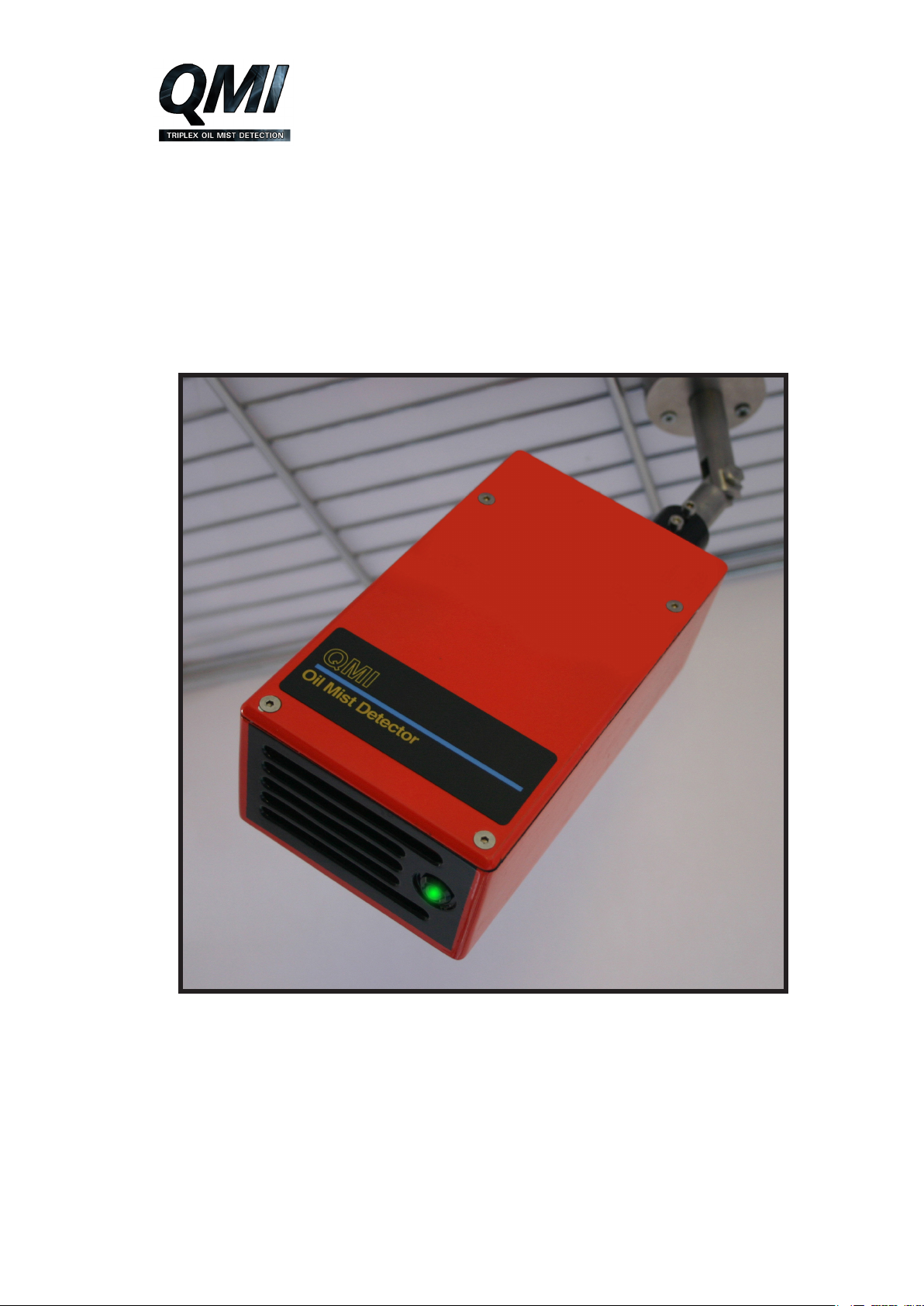
PHOTOGRAPH OF Q10 ATMOSPHERIC SENSOR

Atmospheric Oil Mist Detection System
TM4 / AUGUST 2018
EMAIL [email protected] WEBSITE www.oilmist.com 4 East Barnet Road, London, England, EN4 8RW TEL +44 (0)20 7328 3121
Sheet-10
DRAWING OF Q10 ATMOSPHERIC SENSOR
Inhaltsverzeichnis
Andere QMI Messgerät Handbücher


