QuadTech 1855 Bedienungsanleitung
1855
Capacitor Leakage Current/IR Meter
Instruction Manual
Form 150767/A4
©QuadTech, Inc., 2004
5 Clock Tower Place, 210 East
Maynard, Massachusetts, U.S.A. 01754
October 2006
Telephone 978-461-2100
Sales 800-253-1230
Facsimile 978-461-4295
Website www.quadtech.com
The material in this manual is for informational purposes only and is subject to change, without notice.
QuadTech assumes no responsibility for any error or for consequential damages that may result from the
misinterpretation of any procedures in this publication.
CAUTION
Voltage may be present on front and rear panel terminals. Follow all warnings in this manual when
operating or servicing this instrument. Substantial levels of energy may be stored in capacitive devices
tested by this unit.
!Product will be marked with this symbol (ISO#3864) when it is necessary for the user to refer to
the instruction manual in order to prevent injury or equipment damage.
Product marked with this symbol (IEC417) indicates presence of direct current.
Product will be marked with this symbol (ISO#3864) when voltages in excess of 1000V are
present.

Page 2 of 76

Page 3 of 76
Contents
Warranty ....................................................................................................................5
Specifications ....................................................................................................................7
Accessories ....................................................................................................................11
Safety Precautions...............................................................................................................13
Condensed Operating Instructions....................................................................................15
Introduction - Section 1
1.1 Unpacking and Inspection........................................................................................ 19
1.2 Product Overview .................................................................................................... 19
1.3 Controls and Indicators............................................................................................ 20
1.3.1 Front Panel Controls and Indicators .......................................................... 20
1.3.2 Rear Panel Controls and Connectors ......................................................... 21
1.4 Installation .............................................................................................................. 22
1.4.1 Dimensions ................................................................................................. 22
1.4.2 Instrument Positioning................................................................................ 22
1.4.3 Power Requirements ................................................................................... 22
1.4.4 Safety Inspection......................................................................................... 23
Operation - Section 2
2.1 Terms and Conventions ........................................................................................... 25
2.2 Start-Up.................................................................................................................... 27
2.3 SYSTEM SETUP ................................................................................................... 27
2.3.1 Calibration ................................................................................................. 27
2.3.2 Memory Manage ........................................................................................ 27
2.3.3 System Configuration ................................................................................ 28
2.3.3.1 Test Parameter ........................................................................... 29
2.3.3.2 Beeper ........................................................................................ 29
2.3.3.3 Sound Mode ............................................................................... 29
2.3.3.4 Alarm Mode ............................................................................... 30
2.3.3.5 Trig Delay .................................................................................. 30
2.3.3.6 Trig Edge ................................................................................... 30
2.3.3.7 Handler Mode ............................................................................ 31
2.3.3.8 Contrast ...................................................................................... 31
2.3.3.9 GPIB Address ............................................................................ 31
2.3.3.10 RS232 Baud Rate ...................................................................... 32
2.3.3.11 Key Lock ................................................................................... 32
2.3.3.12 Line Frequency .......................................................................... 33
2.3.3.13 Charge Time .............................................................................. 33
2.3.3.14 Range Dwell .............................................................................. 33
2.3.3.15 Average ...................................................................................... 34
2.3.3.16 EXT Vm Display ....................................................................... 34

Page 4 of 76
Contents
Operation - Section 2 – Continued
2.4 MAIN INDEX ........................................................................................................ 35
2.4.1 Sequence Test ............................................................................................ 35
2.4.2 Step Test .................................................................................................... 36
2.4.3 Null ............................................................................................................ 36
2.4.4 W.V. Test ................................................................................................... 38
2.4.5 Compare ..................................................................................................... 39
2.5 MEAS DISPLAY .................................................................................................... 41
2.5.1 Test Voltage ............................................................................................... 42
2.5.2 Constant Current ........................................................................................ 42
2.5.3 Range ......................................................................................................... 43
2.5.4 Charge Time ............................................................................................... 44
2.5.5 Dwell Time ................................................................................................. 44
2.5.6 Speed........................................................................................................... 45
2.5.7 Trigger ....................................................................................................... 45
2.5.8 Rated Withstand Voltage (Vf) ................................................................... 46
2.5.9 Measurement Time (Tend) ........................................................................ 46
2.5.10 Maximum Charge Time (CHG Tend) ........................................................ 47
2.6 Connection to Device under Test............................................................................. 48
2.7 Measurement Procedure........................................................................................... 49
Interface - Section 3
3.1 RS-232 Interface ..................................................................................................... 51
3.1.1 RS232 Pin Configuration ........................................................................... 51
3.1.2 RS232 Specifications ................................................................................. 51
3.1.3 RS232 Commands ..................................................................................... 52
3.2 IEEE-488 Interface .................................................................................................. 53
3.2.1 Pin Configuration........................................................................................ 53
3.2.2 IEEE-488 Interface Function Codes and Messages.................................... 55
3.2.3 IEEE-488 Interface Commands .................................................................. 57
3.2.4 IEEE-488 Command Format ..................................................................... 59
3.2.5 IEEE-488 Commands - Detailed ............................................................... 60
3.2.6 Error Messages .......................................................................................... 71
3.3 Handler Interface .................................................................................................... 72
3.3.1 Trigger ....................................................................................................... 73
3.3.2 Handler Pin Assignments for Compare Operation .................................... 74
Service & Calibration - Section 4
4.1 General ................................................................................................................... 75
4.2 Instrument Return .................................................................................................... 75
4.3 Calibration ............................................................................................................... 75
4.3.1 1855 Verification Procedure ...................................................................... 76
4.3.2 1855 Verification Data Sheet ..................................................................... 76

Page 5 of 76
Warranty
QuadTech warrants that Products are free from defects in material and workmanship and, when
properly used, will perform in accordance with QuadTech’s applicable published specifications.
If within one (1) year after original shipment it is found not to meet this standard, it will be
repaired, or at the option of QuadTech, replaced at no charge when returned to a QuadTech
service facility.
Changes in the Product not approved by QuadTech shall void this warranty.
QuadTech shall not be liable for any indirect, special or consequential damages, even if
notice has been given of the possibility of such damages.
This warranty is in lieu of all other warranties, expressed or implied, including, but not
limited to any implied warranty or merchantability of fitness for a particular purpose.
SERVICE POLICY
QuadTech’s service policy is to maintain product repair capability for a period of at least five (5)
years after original shipment and to make this capability available at the then prevailing schedule
of charges.

Page 6 of 76
Page 7 of 76
Specifications
Leakage Current Test:
Leakage Current: 0.001uA – 20.0mA
Accuracy: ±(0.3% + 0.005uA)
Test Voltage: 1.0V – 650V DC, 0.1V/Step
Voltage Accuracy: ±(0.5% + 0.2V)
Test Current: 0.5mA – 500mA, 0.5mA/Step for DCV ≤100V
0.5mA – 150mA, 0.5mA/Step for DCV > 100V
Charge Current Accuracy: ±(3% + 0.05mA)
Insulation Resistance Test:
Insulation Resistance: 10Ω– 99.99GΩ
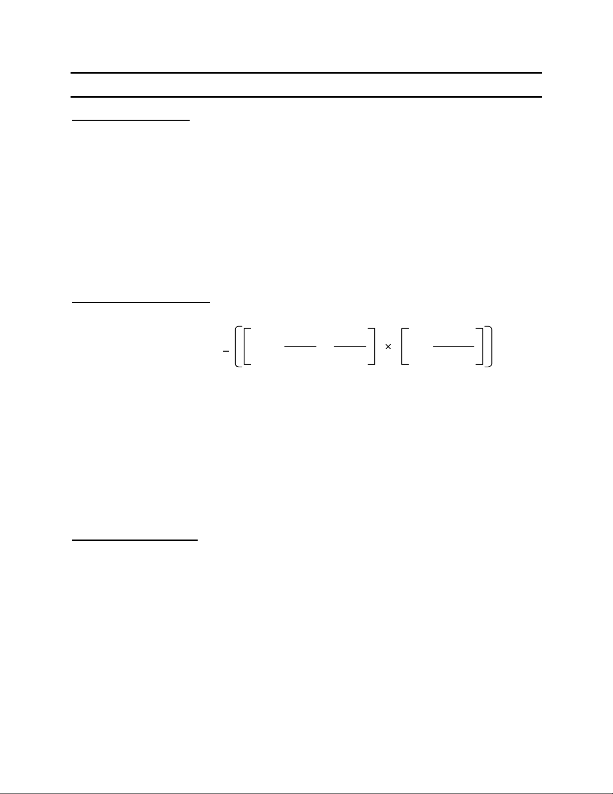
IR Accuracy:
Test Voltage: 1.0V – 650V DC, 0.1V/Step
Voltage Accuracy: ±(0.5% + 0.2V)
Test Current: 0.5mA – 500mA, 0.5mA/Step for DCV ≤100V
0.5mA – 150mA, 0.5mA/Step for DCV > 100V
Charge Current Accuracy: ±(3% + 0.05mA)
Withstand Voltage Test:
Rise Time (Tr): 0.05s – 120s
Withstand Voltage (Vf): 1.0V – 650V DC, 0.1V/Step
Test Current: 0.5mA – 150mA, 0.5mA/Step
Charge Current Accuracy: ±(3% + 0.05mA)
Measure Time: 30s – 600s
MAX Charge Time: 5s – 600s
++ +0.6 20V
Vm 10.005uA
Im
0.5uA
Im %
Where Vm and Im are measured voltage & current for a given load.
+

Page 8 of 76
Specifications (Continued)
General Features
Test Types: Automatic Sequence Test
Manual Step Test
Null: Correction for Lead Leakage
Monitored Voltage (Vm): 1.0V – 650V DC (Voltage across DUT)
Charge Time: 0 – 999seconds in 1s/10s increments <100s; 100s increments >100s
Delay Time: 0.2 – 999seconds in 0.1s increments <100s; 10s increments>100s
Discharge: 65 Watt Discharge Circuit
Trigger: Delay: 0 – 9.995 seconds in 0.1s increments
Edge: Falling or Rising
Measurement Mode: Continuous or Trigger (INT, EXT or Manual)
Measurement Rate: Fast: 18 measurements/second
Medium: 14 measurements/second
Slow: 7 measurements/second
Ranging: Automatic or Hold
Averaging: 1-8 measurements
Compare: Set Upper & Lower Limits for LC and IR Tests
Display: 240 x 64 LCD Graphic display
Indication: Audible alarm programmable HI, LOW or OFF for Pass or Fail
Standard Interface: RS232
Optional Interfaces: IEEE-488 & Handler
Connectors: 1 BNC terminal: Input
2 Banana terminals: HV (+), HV (-)
1 Banana Socket: Chassis Ground
Front Panel Lockout: Keypad Lock

Page 9 of 76
Specifications (Continued)
Mechanical: Bench Mount
Dimensions: (w x h x d): 12.50 x 4.00 x 13.50 inches
317.2 x 101.5 x 342.6 mm
Weight: 18 lbs (8.2kg) net, 22 lbs (10kg) shipping
Environmental: Operating: 10°C to 40oC
Storage: -10°C to 50oC
Humidity: <90%
Pollution Degree 2
Installation Category I
Power: •90-125VAC •190-250VAC
•50 or 60Hz •400W max
Supplied: •Instruction Manual •Power Cable
•Calibration Certificate •Lead Set
Ordering Information: Description Catalog No.
Capacitor Leakage Current/IR Meter 1855

Page 10 of 76
Inhaltsverzeichnis
Andere QuadTech Messgerät Handbücher


