
Roper Whitney U412 Leitfaden
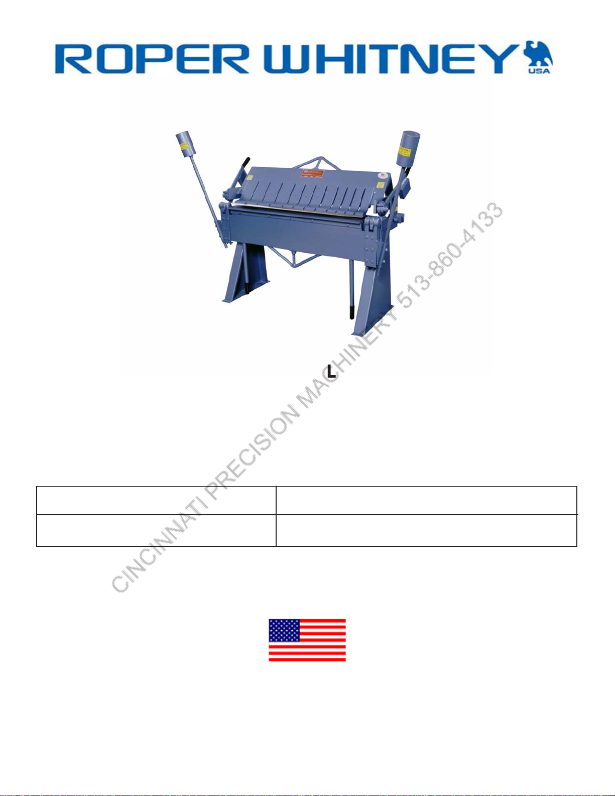
MODEL NO. U412 UNIVERSAL BOX AND PAN BRAKE
OPERATION, PARTS & MAINTENANCE MANUAL
Model: Purchased From:
Serial #: Date Received:
MADE IN THE USA
An American Tradition Since 1910
RoperWhitney/2833HuffmanBlvd./Rockford,IL61103/815-962-3011/Fax815-962-2227
www.roperwhitney.com

FOREWORD
Thismanualhasbeenpreparedfortheownerandoperatorsof Roper Whitney No. U412 brake. Its
purpose,asidefrom operations instructions, is to promote safety through the use ofacceptedoperating
procedures. Readall instructions thoroughlybeforeoperatingthe brake.
Alsocontained in this manual isthepartslist for your brake. It isrecommendedthatonly Roper Whitney
orfactory authorized parts be usedasreplacements.
RoperWhitney/2833HuffmanBlvd./Rockford,IL61103 / 815-962-3011 / Fax 815-962-2227
www.roperwhitney.com
- 2 -
Warranty Statement: 3 YEAR LIMITED WARRANTY
Roper Whitney (“Manufacturer”) warrants, commencing with the date of shipment to first end-user
(“Customer”) and for a period of thirty-six (36) months thereafter, all machinery and parts manufactured
by Manufacturer to be free of defects in workmanship and material. This warranty remains in force for
the above time period only if all of Manufacturer’s operational procedures are followed and
recommended maintenance is performed. If, within such warranty period, any machinery or parts
manufactured by Manufacturer shall be proved to Manufacturer’s satisfaction to be defective, such
machinery or parts shall be repaired or replaced, at Manufacturer’s option. All warranty claims are made
F.O.B Manufacturer’s plant, providing such machinery or parts are returned freight prepaid to
Manufacturer’s plant or designated service center for Manufacturer’s inspection. All failed parts or
components must be returned to Manufacturer prepaid for inspection before credit will be issued for new
parts or components. Manufacturer’s obligation hereunder shall be confined to such repair or replacement
and does not include any charges, direct or indirect, for removing or replacing defective machinery or
parts. No warranty shall apply to machinery, or parts or accessories, which have been furnished, repaired,
or altered by others so as, in Manufacturer’s judgment, to affect the same adversely or which shall have
been subject to negligence, accident or improper care, installation, maintenance, storage, or other than
normal use or service, during or after shipment. No warranty shall apply to the cost of repairs made or
attempted outside of Manufacturer’s plant or designated service center without Manufacturer’s
authorization. No warranty shall apply with respect to machinery or part not manufactured by
Manufacturer, including but not limited to motors, accessories, electrical and hydraulic components, if such
machinery or part is subject to warranty by the manufacturer of such machinery or part. No warranty
claims by Customer will be honored with respect to any machinery or part from which the name and date
plate has been removed or is otherwise no longer located or exhibited on such machinery or part. THE
FOREGOING WARRANTIES ARE IN LIEU OF ALL OTHER WARRANTIES EXPRESSED OR IMPLIED,
INCLUDING, BUT NOT LIMITED TO, ANY IMPLIED WARRANTY OF MERCHANTABILITY AND IMPLIED
WARRANTY OF FITNESS FOR A PARTICULAR PURPOSE. MANUFACTURER SHALL NOT BE SUBJECT TO
ANY OTHER OBLIGATIONS OR LIABILITIES WHATSOEVER WITH RESPECT TO MACHINERY, PARTS,
ACCESSORIES, OR SERVICES MANUFACTURED OR FURNISHED BY IT OR ANY UNDERTAKINGS, ACTS,
OR OMISSIONS RELATING THERETO. UNDER NO CIRCUMSTANCES SHALL MANUFACTURER BE
LIABLE FOR ANY CONSEQUENTIAL OR OTHER DAMAGES, EXPENSES, LOSSES, OR DELAYS HOW SO
EVER CAUSED.
THERE ARE NO WARRANTIES THAT EXTEND BEYOND THE DESCRIPTION ON THE FACE HEREOF.
Note: Consumable tooling is not covered under the 3 year manufacturer’s warranty.
RETURN OF THE PRODUCT REGISTRATION CARD FURNISHED WITH THE PRODUCT IS NECESSARY TO OBTAIN
WARRANTY COVERAGE THEREON. CARD MUST BE FULLY COMPLETED, SIGNED BY THE PURCHASER, AND IF
APPLICABLE, SIGNED BY THE DISTRIBUTOR. RETURN REGISTRATION CARD TO:

SAFETY INSTRUCTIONS
1. Knowthe safety and operating instructions containedinthisbrochure. Become familiar with and
understandthelimitationsof this machine. Always practicesafety.
2. Wearapprovedeyesafety protection such as glasses, goggles, etc., when operating the brake to
protectyour eyes.
3. Wearprotectivefootwear or safety shoes.
4. Keep your hands clearofthe nose bar and clamping area of thebrake. Keephands clear of the
apronareaofthe brake when making bends.
5. Whenbendingcapacitymaterialuse your legs and arms for making the bend, similar to lifting a
heavyobject,to avoid back strain. Maximum length and capacity material is atwopersonjob.
Adjustthe counterweightstoprovidemaximum assistanceonheavy bends.
6. Neveruseapipeorbar on the clamp handles or apron handles for additional leverage.
7. Donotpush or pullonthe counterweights duringthebending process. The counterweightsintended
purposeistoreducetheforcerequiredtolifttheapron.
8. Keepclearofthe counterweight and apron swing area while operating thebrake.
9. Keep the work area around the brake clear and clean to avoid slipping or tripping.
- 3 -

SAFETY LABELS
Do not operate the U412 Brake without the proper safety labels in place. If your machine is
missingthe following labels,pleasecontact Roper Whitney Co.oryour authorized RoperWhitney
distributortoorder.
- 4 -

INSTRUCTIONS
MODEL U412 CONNECTICUT FLOOR BRAKE
LeveltheBrake and shim under the feet to avoiddistortion. Fastenfirmlyinplace. Thefront feet must be
wellfastenedtoavoidtippingwhenbendingforceisappliedtohandles. Seespecialnotesonleveling
FloorModelHandBrakes.
TheModelU412isratedfor bending 48” of 12 gauge mild steel, 1 inch flange, with bending angle and
bendingbarfastened securely in place. The beam (upper clamping member) may beadjustedtothe
rearamaximumof 1 1/8”. When adjusting to bend 12 gauge material, swing the apronupto90degrees
andsetthebeam adjustment to allow a clearance of 3/16” between the apron edge and the radius bar.
Forlightermaterial,aclearanceof11/2to2timesmaterialthickness should be used. Soft aluminum
maybe formed with clearance equal tomaterialthickness.
Ratedcapacityforstainlesssteelis16gauge. Clearanceshould be at least twice material thickness.
Removingthebendingangle for narrow or offset bends, reduces capacity to 16 gauge mild steel. Re-
movingboth bending angle and bending bar reduces capacityto 20gauge. Avoidusing the brake
withoutthebendingbarasmuchaspossibleasthebar is made of tough material to protect the apron
edgefromwear.
Clampingpressure is controlled by nuts onthelowerendof the toggle bolt. This pressure shouldbe
adjustedwithasmallpieceofmaterialtobebentclampedineachendofthemachine. Movethenutsso
thatthelevers (No. 10 & 11), pull against the stopswith an equal effort. Excessiveclampingpressureis
notrequired. Use only enoughtoholdthe material firmlyinthebrake.
TheseBrakesare notintended for bending rods,wires, multiple thicknessesor across lockseams.
Operationsof this type will result indentingtheedgeof the apron and springing themachineoutofline.
Lubricatethemoving parts of the machine with lightgreaseorheavyoil. Lasting accuracy depends on
properlubrication.
SPECIFICATIONS
Lengthofbed 48”
Capacityonmild steel, 1” flange,
Withbendingbarandangleinplace 12 ga.
Withbending angle removed 16 ga.
Withbendingbar and angle removed 20 ga.
Minimumreversebend (bar & angle removed) 1/4”
Maximum liftof beam 1 5/8”
Front torear adjustmentofbeam 1 1/8”
FingerWidths 3”,4”,5”
Maximumdepth ofbox 6”
Shippingweight 1400 lbs.
Packing Wood skids & blocking
-5-

NOTES ON LEVELING FLOOR MODEL U412
Forproper adjustment, maintaining accuracy,andsafety to the operator,thebrake must be leveland
securelyboltedto the floor. Do not leavethemachineontheoriginal shipping skid.
PreliminaryLeveling:
1. Relievealltensionon bed nut (No. 2) andsetscrew(No.27).
2. Raisethebeamtoitsmaximum height by means of eccentric levers (No. 10 & 11).
3. Usinganaccuratespirit level or protractor head level on the bed bar(frontofbed),
shimunder the legs untilthebedbar is level fronttorearand lengthwise, with floorbolts
tightenedagainst the shims.
Thebrake may change shapeslightlyintransit. Therefore, it is advisabletofurthercheck the level as
follows:
1. Relievealltensionon beam nuts (No. 1),andsetscrew (No. 27).
2. Lowerthebeamontothebedandloosennut(No. 33) so there is 1/4” space between bottom of
pin(No.31) and top surface of nut(No.33).
3. Startingwithscrewsfinger tight, takeup screws(No.27) about one fullturn.
4. Startingwithnuts (No. 1 &2)fingertight,takeupeachabout 3/4 turn.
5. Lookingthroughfromtherear of the brake, the beam and bed shouldbeincontactatthe center
andshowingacrack of light at each end, as in Fig. 1. If there is less light showingatoneend,
loosenthe rear floorboltat that endandshim under theleguntillight shows evenlyatboth ends.
6. Theabovesteps should resultina level machine,butnot necessarily theproperadjustment for
yourwork. Toadjustforstraight bendinganduniform radius, followthesubsequent
PRELOADING ADJUSTMENTS.
-6-

PRELOADING ADJUSTMENTS FOR FLOOR MODEL U412
Removetheshipping skids, bolt the brake to the floor, and level according to NOTESONLEVELING
FLOORMODEL U412.
Loosenstrap bolt nuts (No. 1 & 2). Loosentierod screws (No. 27). Raise the beam tomaximum height
bymeansofeccentriclevers(No.10&11).
Thetopedgeoftheapronshouldbe1/64”belowthe edge of the bed at the ends. If it is not, the hinge
boltsshouldbeadjustedto bring the apron to this position. Tighten hinge boltssecurelyafterthis
adjustment.
Tighten apron strap bolt(No.2)untiltheapron edge is 1/32” above the bed edgeatthecenter. Itshould
remain1/64”belowthebedatthe ends.
Takeup the tie rodscrews(No.27) about one fullturn,startingwithfinger tight.
Tighten bed strap bolt (No. 2) untiltheedgeofthebedis1/64”abovethetopoftheapronatcenter. This
shouldbringapron and bed parallel fromendtoend,withthe bed 1/64” higher.
Beampreloadingshouldbeminimalinorderto avoid counteracting the preload in the bed. Strapnuts
(No.1) may be tightenedfrom1/4to 1/2 turn, startingwithfingertight.
Thebrakenow is adjusted for average work. When bendingverylightmaterial,itmay be necessary to
reducepreloadingin the bed and apron by slackingoffstrapnuts(No.2). On full capacity work,
preloadingofbedand apron may be increased to tighten the bend radius at thecenterand produce a
straightbend. Beamstrap nut (No. 1) also is effectivein tightening the radius atthecenter.
Hemmingof heavy material mayrequireaddingpressure in the centerofthebeam by tighteningnut
(No.1). Excessive clamping pressurebytighteningnut (No. 33)willnothelp. It only defeatsthepurpose
ofpreloadingandputsextremestressonthetoggle(No. 45 & 46). No amount of preloading will
compensatefor incorrect clamping pressure.
Followcarefully the generalinstructionsfor adjustingclampingpressureand clearancesforvarious
thicknessesofmaterial. Too little clearance resultsinsharpbendsatthe ends, larger radius at the cen-
ter, and a bendthatisnotstraight. Itisbettertoaccept a slightly greater radius in order to get a straight
bend.
-7-

EXAGGERATED VIEW OF CROWN
FROM REAR OF BRAKE
FIG.I
FIG.II
-8-

-9-

-10-
Inhaltsverzeichnis


