Size Stream SS20 Bedienungsanleitung

22
919.650.2525
info@sizestream.co
SizeStream.com
223 Commonwealth Court
Cary, NC 27511
FEBRUARY 21, 2020
SOFTWARE V6.0
This manual outlines the steps to assemble the
Size Stream Classic SS20 3D Body Scanner.
SS20 CLASSIC
SCANNER
ASSEMBLY MANUAL

Classic Assembly Manual
1
Table of Contents
ASSEMBLE THE TOOLS NEEDED: ................................................................................................................................................................................... 3
SCANNER LOCATION REQUIREMENTS: .......................................................................................................................................................................... 3
UNPACK THE CRATE....................................................................................................................................................................................................... 4
PLACING THE SCANNER CARPET.................................................................................................................................................................................... 5
LOWER RIGHT CONNECTOR BAR & FRONT SENSOR ASSEMBLY .................................................................................................................................... 5
LOWER LEFT CONNECTOR BAR...................................................................................................................................................................................... 6
BACK-SENSOR ASSEMBLY. ............................................................................................................................................................................................. 7
UPPER LEFT CONNECTOR BAR ...................................................................................................................................................................................... 8
UPPER RIGHT CONNECTOR BAR .................................................................................................................................................................................... 9
RIGHT & LEFT HANDHOLD BARS .................................................................................................................................................................................. 10
HANDHOLD ASSEMBLY................................................................................................................................................................................................. 12
INSTALLING THE MONITOR. ........................................................................................................................................................................................ 13

Classic Assembly Manual
2
SCANNER’S COMPUTER .............................................................................................................................................................................................. 14
ROUTING THE SENSOR CABLES .................................................................................................................................................................................. 16
CONNECTING POWER .................................................................................................................................................................................................. 17
ALIGNMENT BOARD STORAGE..................................................................................................................................................................................... 19
SCANNER ALIGNMENT BAR ......................................................................................................................................................................................... 20
CURTAIN TRACK ........................................................................................................................................................................................................... 21
FRAME CURTAIN ........................................................................................................................................................................................................... 22
HANG THE DRESSING ROOM CURTAIN......................................................................................................................................................................... 23
COMPLETED. ................................................................................................................................................................................................................ 23

Classic Assembly Manual
3
Tools Needed:
Drill with #2 and #3 size Phillips screwdriver bits or a manual Phillips screwdriver
7/16” wrench or an adjustable wrench or pliers
Utility knife or pair of scissors
Stepladder.
Standard computer power cable that is compatible with local AC power
Scanner Location Requirements:
1. Stable and level ground.
2. Temperature controlled room.
3. No HVAC vents blowing directly into the scanner.
4. No direct lighting or direct sunlight in the scanner.
Important
Do not assemble the scanner
alone.Two people are
recommended for assembly.

Classic Assembly Manual
4
Unpack the Crate…
1. Remove all parts and components from the crate.
2. Review parts and components against the provided packing list.
3. Remove the step-by-step hardware set from the accessory box.

Classic Assembly Manual
5
Placing the Scanner Carpet
1. Position the carpet where the scanner will be located.
2. Orient the carpet so the footprints will be facing the computer pan.
Lower Right Connector Bar & Front Sensor Assembly
1. Use four (4) ¼-20 x 5” Pan Head Machine Screws to attach the Front Sensor
Assembly to the Lower Right Connector Bar.
Qty
Hardware Name
4
1/4-20 x 5” Pan Head Machine Screw
”
ASSEMBLY TIP
Do not fully tighten any of the
¼-20 x 5” Pan head machine
screws around each corner until
instructed.
ASSEMBLY TIP
The shorter section of the
connector bars attaches to the
Front Sensor Assembly.The
longer section attaches to the
Back-Sensor Assembly
Front Sensor
Assembly
Lower Right
Connector Bar
Computer Pan
Classic Assembly Manual
6
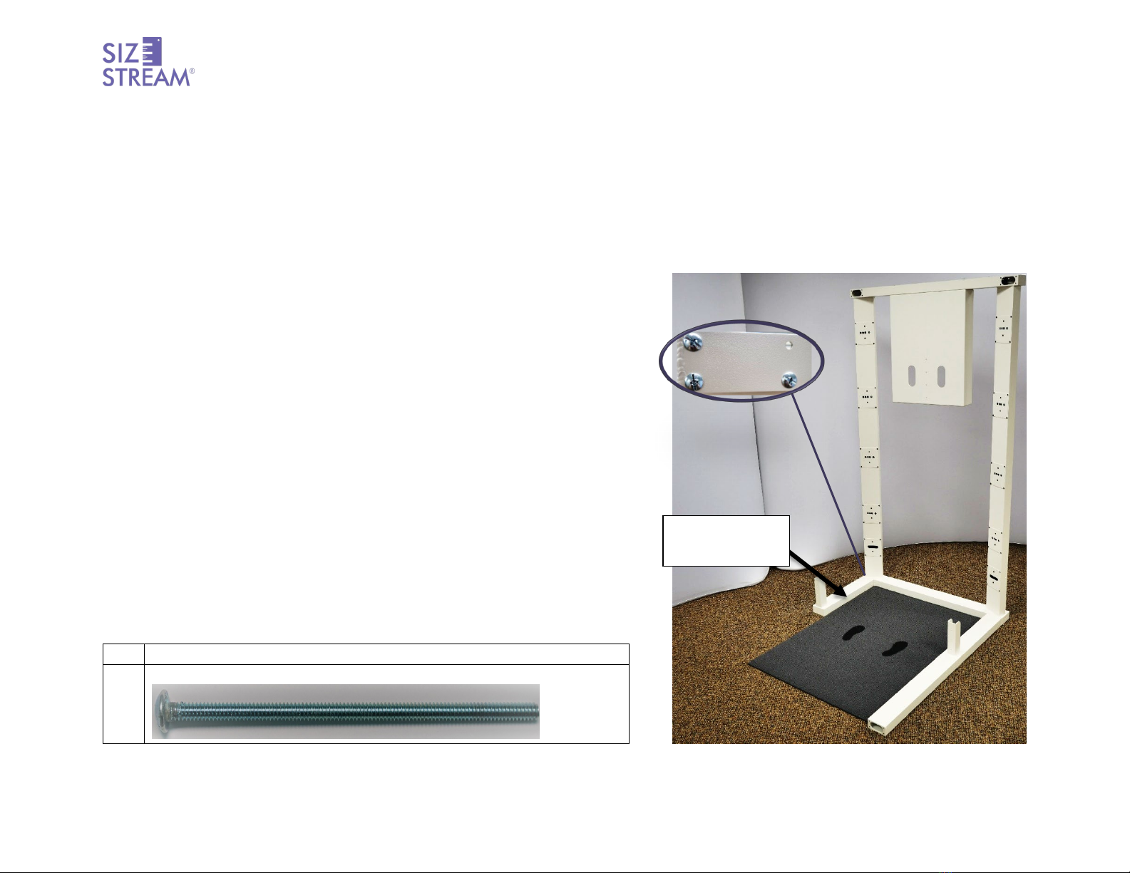
Lower Left Connector Bar Assembly.
1. Use four (4) ¼-20x5” Pan Head Machine Screws to attach the Lower Left Connector Bar to the Front Sensor Assembly
Qty
Hardware Name
4
1/4-20 x 5” Pan Head Machine Screw
”
Lower Left
Connector Bar

Classic Assembly Manual
7
Back-Sensor Assembly.
1. Use four (4) ¼-20 x 5” Pan Head Machine Screws to attach the Back-Sensor Assembly to the Lower Right Connector Bar.
Qty
Hardware Name
4
1/4-20 x 5” Pan Head Machine Screw
”
Back Sensor
Assembly
Lower Right
Connector Bar

Classic Assembly Manual
8
Upper Left Connector Bar
1. Use six (6) ¼-20 x 5” Pan-Head Machine Screws to attach the Front and Back
Sensor Assemblies to the Upper Left Connector Bar.
Qty
Hardware Name
6
1/4-20 x 5” Pan Head Machine Screw
”
ASSEMBLY TIP
To facilitate routing of the sensor
cables through the frame to the
computer, do not install the
screws in the top inside holes at
each corner. Once the sensor
cables have been routed around
the corner, the top inside screws
can be installed.
ASSEMBLY TIP
The shorter section of the
connector bar attaches to the
Front Sensor Assembly . The
longer section attaches to the
Back-Sensor Assembly.
Upper Left
Connector
Bar

Classic Assembly Manual
9
Upper Right Connector Bar
1. Use six (6) ¼-20 x 5” Pan Head Machine Screws to attach the Front and Back
Sensor Assemblies to the Upper Right Connector Bar.
Qty
Hardware Name
6
1/4-20 x 5” Pan Head Machine Screw
”
ASSEMBLY TIP
To facilitate routing of the sensor
cables through the frame to the
computer, do not install the
screws in the top inside hole at
each corner. Once the sensor
cables have been routed around
the corner, the top inside screws
can be installed
Upper Right
Connector
Bar
Andere Handbücher für SS20
1
Inhaltsverzeichnis
Andere Size Stream Scanner Handbücher


