SMART MATERIAL HVA1500 Bedienungsanleitung

VERSION 2.0 AUGUST 2021
HVA1500/50
User Manual
Version 2.0

Page2 https://www.smart-material.com
HVA 1500/50 User Manual V2.0
Contents
1. Safety Instructions AND Symbols
READ First .......................................................................Page3
2. Overview.........................................................................Page5
3. INSPECtion & Installation ................................................Page6
3.1 What comes with thE HVA1500/50 . . . . . . . . . . . . . . . . . . . . Page6
3.2 incoming inspection . . . . . . . . . . . . . . . . . . . . . . . . . . . Page6
3.3 INSTALLation . . . . . . . . . . . . . . . . . . . . . . . . . . . . . . . Page6
4. SPecifications .................................................................Page7
4.1 General Specifications . . . . . . . . . . . . . . . . . . . . . . . . . Page7
4.2 Output voltage, Maximum current performance . . . . . . . . . . . . Page7
4.3 Wave Generator Input . . . . . . . . . . . . . . . . . . . . . . . . . . Page8
4.4 audio signal input . . . . . . . . . . . . . . . . . . . . . . . . . . . . Page8
4.6 output current monitor . . . . . . . . . . . . . . . . . . . . . . . . . Page8
4.7 Indicators . . . . . . . . . . . . . . . . . . . . . . . . . . . . . . . . Page8
4.8 interlock . . . . . . . . . . . . . . . . . . . . . . . . . . . . . . . . . Page9
4.9 EU-Compliance Declaration . . . . . . . . . . . . . . . . . . . . . . . Page9
5. operation......................................................................Page10
5.1 Front Panel controls . . . . . . . . . . . . . . . . . . . . . . . . . Page10
5.2 Rear panel controls . . . . . . . . . . . . . . . . . . . . . . . . . . Page12
5.3 Operational requirements. . . . . . . . . . . . . . . . . . . . . . . Page13
5.4 operating mode. . . . . . . . . . . . . . . . . . . . . . . . . . . . . Page13
6. Further Resources ........................................................Page14
6.1 Contacts . . . . . . . . . . . . . . . . . . . . . . . . . . . . . . . . Page14
6.2 limited Warranty . . . . . . . . . . . . . . . . . . . . . . . . . . . Page16

Page3 https://www.smart-material.com
HVA 1500/50 User Manual V2.0
To ensure safe operation and to keep the operator and the product safe,
THE INFORMATION, CAUTIONS, AND WARNINGS IN THIS
MANUAL MUST BE HEEDED.
WARNING – WARNING STATEMENTS AND SYMBOLS IDENTIFY
CONDITIONS OR PRACTICES THAT COULD RESULT IN INJURY OR
LOSS OF LIFE.
CAUTION – CAUTION STATEMENTS AND SYMBOLS IDENTIFY
CONDITIONS OR PRACTICES THAT COULD RESULT IN DAMAGE TO
THIS PRODUCT OR OTHER PROPERTY.
REVIEW THE FOLLOWING SAFETY PRECAUTIONS TO AVOID INJURY AND
PREVENT DAMAGE TO THIS PRODUCT OR ANY PRODUCTS CONNECTED
TO IT. TO AVOID POTENTIAL HAZARD, USE THIS PRODUCT ONLY AS
SPECIFIED.
• Only qualied personnel should operate and make connections to this
unit.
• All connections including removal of any connections from the High
Voltage Output Connector must be done with the unit OFF and discon-
nected from the AC line source.
• To avoid shock hazard, electrocution, or re, observe all ratings and
markings on the product. Consult the User’s Manual for further safety
information before making connections to the product.
The High Voltage Amplier HVA 1500/50 generates voltages up to 1500V.
These voltages are present inside the unit and at the rear panel output
connectors and are a danger to life if used improperly.
Make sure that attached cables are electrically and mechanically NOT
defective. Replace cables only with the high voltage amplier switched o.
Before switching the high voltage amplier on, make sure that all cables are
connected to the corresponding socket of the load.
1. Safety Instructions AND Symbols
READ First

Page4 https://www.smart-material.com
HVA 1500/50 User Manual V2.0
Before removing the cables from the load, switch o the amplier and wait
at least 10 minutes until the load capacitors are discharged.
Never operate the high voltage amplier if any housing part of the unit is
defective or removed.
Do not open the high voltage unit. Only qualied personnel may open the
unit.
Warning!
HAZARDOUS VOLTAGES UP TO 1500V ARE
PRESENT AT THE HIGH VOLTAGE AMPLIFIER’s
OUTPUT.
TAKE APPROPRIATE PRECAUTIONS DURING
MEASUREMENT PROCEDURES.
BEFORE TURNING ON THE AMPLIFIER, REMOVE
HANDS AND ALL TEST EQUIPMENT FROM THE
LOAD AND CONNECTED CABLES!!

Page5 https://www.smart-material.com
HVA 1500/50 User Manual V2.0
The HVA1500/50 is a single channel, high voltage power amplier. The
power amplier is capable of delivering an output voltage in the range of
-500 V to +1500 V with an output current of up to 50 mA DC.
The amplier provides a large signal bandwidth of DC to 10 kHz depending
on the load capacitance and has a gain of 200 V/V.
Two independent signal inputs are provided, a wave generator input and
an audio signal input which can be selected by a rotary switch. The wave
generator input accepts signals in the range of -2.5 V to +7.5 V at a
frequency of 0 Hz to 10 kHz.
The audio signal input accepts audio signals in the range of 0.2 V to 3 V AC
at a frequency of 10 Hz to 10 kHz. Two potentiometers are also provided to
adjust the gain and the oset of the audio signal.
The monitoring circuitry allows output voltage and output current
monitoring. Both monitoring signals are near ground potential, i.e. not
hazardous, low voltages.
Two LEDs indicate the states of the output voltage/current. A LED for
“HV On” and a LED for “Limit”. The LED “HV On” illuminates if the output
voltage is enabled by a rotary switch or by an interlock signal.
The LED “Limit” illuminates if the output voltage/current exceeds the limits.
The interlock circuitry allows switching o and on the high voltage by an
external signal.
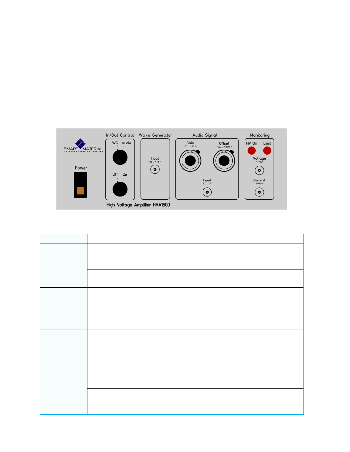
Fig 1: HVA1500/50 front panel
2. Overview

Page6 https://www.smart-material.com
HVA 1500/50 User Manual V2.0
This section provides information for incoming inspection, damage claims,
shipping, and installation of the HVA1500/50.
3.1 What comes with thE HVA1500/50
The HVA1500/50 package contains the following items:
• Single channel high voltage amplier unit HVA 1500/50,
• Line voltage cord,
• High voltage cable with an SHV plug,
• 3-pin interlock connector,
• User Manual.
3.2 incoming inspection
The high voltage amplier unit should be inspected for damage, scratches,
dents, or other defects. Also the cushioning materials should be checked
for sign of severe stress. The electrical performance of the amplier unit
should be veried upon receipt. Make sure that no cable is electrically
and mechanically defective. If the unit is damaged in transit, or fails to
meet the specications upon receipt, notify the carrier and the sales oce
immediately. Retain the shipping carton and padding material for the
carrier’s inspection. The sales oce will arrange for replacement or repair
of your unit without waiting for claim settlement against the carrier. Before
returning the high voltage amplier for any reason, notify the sales oce of
the diculty encountered. They will send shipping instructions.
3.3 INSTALLation
The AC power supplied to the amplier unit should be 90 to 264 VAC, 47 to
63Hz, single phase. Two 2-ampere slow blow fuses of 1.6A are used.
For safety reasons, the power supply must be grounded through the AC
power cord. When operating from ungrounded power sources, a secondary
grounding method is mandatory. Before operation, make sure that the
output cable of the amplier unit is connected to the load.
The cooling of the control unit is provided by convection. The location of the
unit must ensure adequate air circulation.
3. INSPECtion & Installation

Page7 https://www.smart-material.com
HVA 1500/50 User Manual V2.0
4.1 General Specifications
The HVA1500/50 is designed to be operated as a high voltage power supply
for the MFC, P1 type products.
AC Power supply
90-264VAC, 47-63 Hz, 150VA
Slow fuse 1.6A
Standard three prong connector
Operating Conditions Ambient Temperature 0°C to 40°C
Relative Humidity up to 85%, noncondensing
Mechanical
255 mm W x 100 mm H x 400 mm D
Components are mounted on both sides of the PB
Weight approx. 8kg
Input Impedance All input impedances are 100kOhm
4.2 Output voltage, Maximum current performance
Output Voltage Range -500 V to +1500 V
Variable Current Range 0 to +/- 50 mA DC
0 to 60 mA peak AC
Output Connector SHV Female Connector
DC Voltage Gain 200 V/V for wave generator input, noninverting
DC Voltage Gain Accuracy Better than 0.1% of full scale
Oset Voltage Less than 1 V
Slew rate Greater than 50 V/μs
Large Signal Bandwidth DC to 10 kHz
Drift with Time Less than 100 ppm/hr
Drift with Temperature Less than 50 ppm/°C
Warm up Time 5 min
Connector +500V, 0mA to 10mA, 5W
4. SPecifications

Page8 https://www.smart-material.com
HVA 1500/50 User Manual V2.0
4.3 Wave Generator Input
Input Voltage Range -2.5 V to +7.5 V,
corresponds to -500 V to +1500 V output
Input Resistance 100 kOhm
Signal Frequency Range 0 Hz to 10 kHz
Input Connector BNC coaxial connector
4.4 audio signal input
Input Voltage Range 0.2 V to 3 V AC
Input Resistance 100 kOhm
Gain Control Range -12 db to +12db,
by using the 10-turn potentiometer Gain
Oset Control Range -500 V to +1500 V,
by using the 10-turn potentiometer OFFSET
Signal Frequency Range 10 Hz to 10 kHz
Input Connector BNC coaxial connector
4.5 output Voltage monitor
Conversion Factor 1/200th of the output voltage Output
Output Impedance 1 kOhm
Output Connector BNC coaxial connector
4.6 output current monitor
Conversion Factor 0.2 V / mA
Output Impedance 1 kOhm
Output Connector BNC coaxial connector
4.7 Indicators
HV On LED The LED illuminates indicating that the
high voltage is on
Limit LED The LED illuminates if the output voltage or current
exceeds the maximum limits

Page9 https://www.smart-material.com
HVA 1500/50 User Manual V2.0
4.8 interlock
Function
The output voltage is turned on only if the
interlock signal is closed , i.e. pin 1 and pin 2 of
the interlock connector are connected together
Interlock Connector A 3-pole socket on the rear panel
Signals Pin 1: output signal, +5 V
Pin 2: input signal, i.e. interlock signal
4.9 EU-Compliance Declaration
The high voltage amplier MFC1500/50 has the CE-marking.
The EU Declaration of Conformity ensures that the device meets the
requirements of the European Standard given by the regulation of the
Council of the European Union for assimilation of the legal regulations
of the members of the European Union concerning the Electromagnetic
Compatibility (89/336/EEC). Conformity is shown by the compliance with
the concerning standards EN 50081-1; EN 50082 or EN50081-2; EN 50082-
2 respectively.
Page10 https://www.smart-material.com
HVA 1500/50 User Manual V2.0
This section outlines the general procedure for operating the high voltage
amplier and the load. For more operating information, see also the manual
for any used piezo actuators.
5.1 Front Panel controls
Fig 2: HVA1500/50 front panel
Power Toggle Switch Turns the power supply on and o.
In/Out
Control
WG/Audio Switch
This rotary switch enables the wave
generator input or the audio signal
input.
On/O Switch This rotary switch turns the output
voltage on or o.
Wave
Generator Input Signal
The Wave Generator input accepts
signals in the range of -2.5 V to +7.5 V
at a frequency of 0 Hz to 10 kHz,
which corresponds to an output voltage
of -500 V to +1500 V.
Audio
Signal
Input
Input Signal The audio signal input accepts signals
in the range of 0.2 V AC to 3 V AC at a
frequency of 10 Hz to 10 kHz.
Gain Potentiometer This potentiometer allows the gain
adjustment in the range of
-12 db to +12 db, i.e. a gain factor of
1/4 to 4.
Oset Potentiomter This potentiometer allows oset
adjustments in the range of
-500 V to +1500 V.
5. operation
Dieses Handbuch passt für folgende Modelle
1
Inhaltsverzeichnis
Andere SMART MATERIAL Verstärker Handbücher


