2
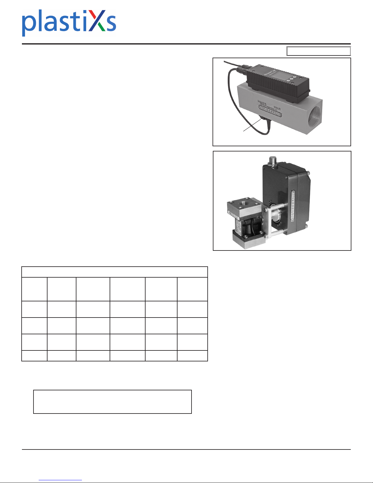
Tracer®
VMA with AutoReg™Instruction
Power supply other than 24VDC may damage the electronics! Ensure
that power supply provides Earth Ground (0V) and not a reference.
Earth Ground is required for reliable ow and temperature outputs.
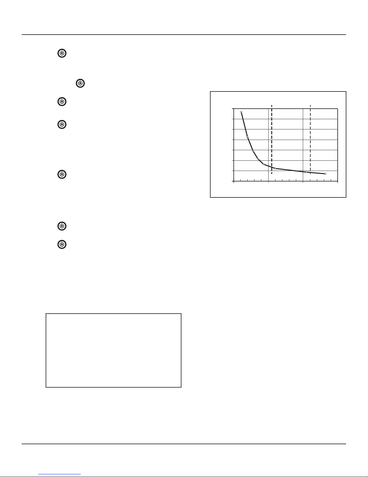
“TF” notication appears on the display when Turbulent Flow is likely
inside the cooling circuit of the selected size.
Turbulent ow is the mixing and swirling of water inside a cooling line
that provides optimum heat transfer. Water ow rate greater than the point
of Turbulent Flow provides diminishing benets with increased pumping.
Turbulent ow tracking allows technicians to apply mathematical cool-
ing principles to all machines in a water system. Visit the Technical
Documents section of www.smartow-usa.com for a detailed discussion of
Turbulent Flow.
Input the percentage of glycol (0, 10, 20 or 30% only) in cooling water for
accurate Turbulent Flow Indication (default value is 0). See Setup Mode
option on page 5. Antifreeze compounds of ethylene glycol are sometimes
added to cooling water. Glycol compounds have much higher viscosity
than water. As a result, higher ow rates are required to reach Turbulent Flow
when glycol is used.
Pipe Conguration
For best performance, install a straight run of pipe equal to 10 pipe
diameters on the inlet side of the TracerVMA owmeter and a straight run of
pipe equal to 5 pipe diameters on the outlet side of the owmeter.
Use appropriate pipe sealant to prevent leakage on inlet and outlet sides of
the owmeter.
Power
Attach the power and switching connections to the bare wires of the cable
according to the chart at right. Individual wires are 24AWG stranded
copper. Attach 24VDC power to the unit for correct operation.
In normal operation, the internal relay is energized. If power to the unit is
lost, or if unit is turned o, relay state changes to signal an alarm.
EMI/RFI Interference
Care should be taken to route power and signal cables away from motors
and pumps. Signal integrity may be adversely aected by close proximity
of the wiring to machinery producing high frequency emissions.
BTU Basics
To obtain the most accurate BTU/m calculation, use the
Tracer VMA to measure the supply side water temperature (in °F)
before installing in a cooling water return line.
BTU’s per minute calculation is based on the increase in water temperature
multiplied by the ow rate. The TracerVMA calculates this information
based on supply side temperature entered manually. Due to inherent dier-
ences in most thermometers, the most accurate BTU calculation will result
from using the same thermometer (inside the TracerVMA) to measure supply
and return line temperatures. Record the supply side temperature and enter
it using the “Set BTU/m Input Temperature” instructions on page 5.
Turbulent Flow
Cable
Maximum eective signal cable length is 4.8M (16ft)
as supplied. Splicing extra length to the cable is not
recommended.
Flow and Mounting Direction
Orient the TracerVMA User Interface so the ow
direction of the process uid matches the directional
arrow on the body of the meter. Flow in the opposite
direction of the arrow will yield inaccurate voltage
output. The presence of air bubbles in the process uid
will also create an inaccurate voltage output.
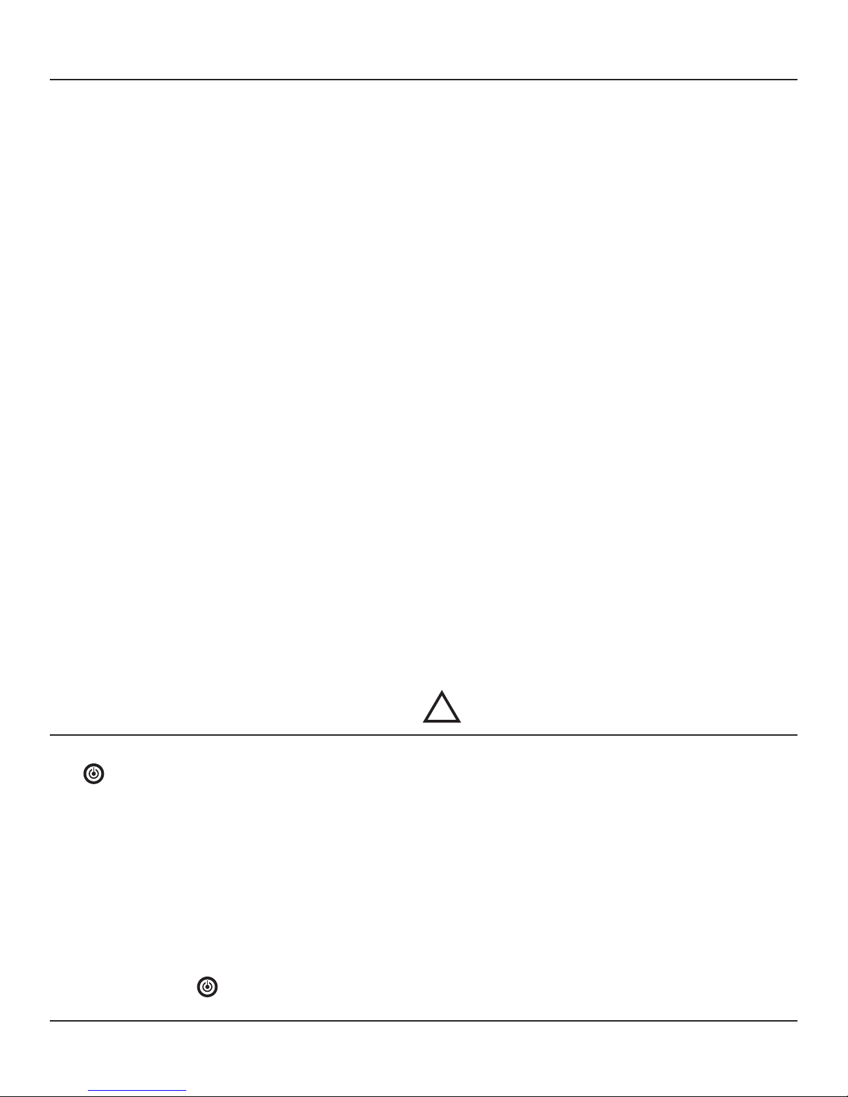
Install AutoReg module downstream from the User
Interface at least 5 pipe diameters from the sensor
outlet. Flow regulator response time will increase in
relation to distance between AutoReg module and
TracerVMA User Interface.
Maintenance Instructions
Copper Plumbing Alert
DO NOT connect an aluminum body owmeter
directly to copper plumbing. Galvanic corrosion is very
likely to occur. Stainless steel body material is strongly
recommended for this application.
9-Conductor Cable Color Chart
Wire Color Function
Black DC Ground (Earth)
(Ground for Analog Output)
Yellow +DC Input (24VDC)
Red not used
Blue not used
Orange Flow Analog Voltage Output (+)
Violet Temp. Analog Voltage Output (+)
Green Relay Common
Brown Relay Normally Open
Gray Relay Normally Closed