SPL-Laboratory Race Meter 2018 Bedienungsanleitung

Spl-Lab Race Meter
User Manual
A new device for measuring the performance of a car or motorcycle.
2018
Kirill Berezin
SPL-Laboratory
01/01/2018

2
Table of Contents
Table of Contents ............................................................................................................................2
Purpose of the device.......................................................................................................................3
Description...................................................................................................................................3
Ergonomics..................................................................................................................................3
Exploitation of the device................................................................................................................4
Important safety information:......................................................................................................4
Identifying the functional parts of the device:.............................................................................5
Starting work with the Race Meter..............................................................................................6
Device Operation Modes.................................................................................................................8
SPD mode for measuring acceleration or deceleration................................................................9
LP mode for measuring lap time................................................................................................10
DST mode for measuring time required for covering the specified distance ............................11
LOG mode for setting telemetry logging parameters................................................................12
CFG mode for the device configuration ....................................................................................14
USB mode for transmitting data from SD card .........................................................................15
Firmware upgrade using PC..........................................................................................................16

3
Purpose of the device
Description
Race Meter –A new device for measuring the performance of a car or motorcycle. The device is
an equivalent of RaceLogic though not inferior to it in accuracy and ease of operation. The
device is easy-to-use and it does not require additional equipment. For measuring acceleration,
simply connect the device to the cigarette lighter of a car. The device should be attached to the
windshield of a car using suction cups, which allows taking measurements while you are driving.
Apart from GPS/GLONASS receiver, Race Meter has an acceleration sensor, which allows
logging acceleration data. The device has a micro-SD slot for logging your laps in universal data
formats VBO, NMEA and TXT. Logged data can be uploaded for analysis into popular
programs such as RaceLogic PerformanceBox, VBOX Power Suite, Circuit Tools, Harry's
LapTimer, Google Earth, etc. Telemetry can be transmitted to a PC via USB port in real time.
The device can be connected as a card-reader for easy transfer of data to a PC, tablet or
smartphone. Race Meter is, probably, the most compact acceleration meter on the market.
Ergonomics
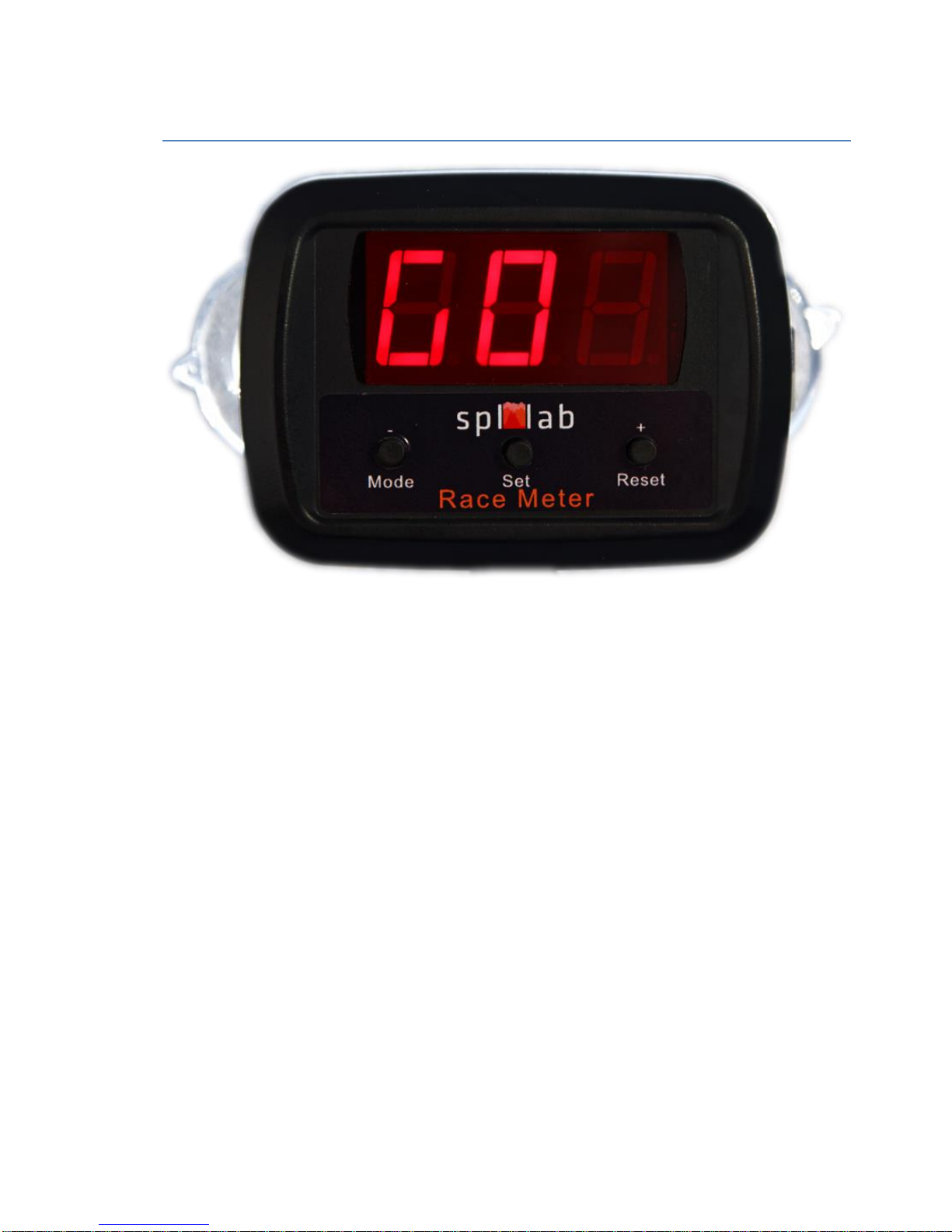
The car acceleration meter, Race Meter, has a mobile enclosure that has a red three-segment
display, 3 control buttons, and Mini-USB slot for the power supply and updating the internal
software. The device should be attached to the windshield of a car using the two suction cups at
the back of the device. It does not require any additional equipment.

4
Exploitation of the device
Important safety information:
!Please follow all safety precautions and common sense when racing.
!Take measurements only on specially assigned roads.
!Do not try taking measurements while driving in densely populated areas and on public roads.
!Use extreme caution while taking measurements while driving.
!Take measurements only in good weather conditions; heavy precipitation can impair
measurement accuracy and lead to traffic accidents.
!The manufacturer does not bear responsibility for damage, caused directly or indirectly, as a
result of improper use of the device.
!Before using the device, examine its enclosure for cracks and splits, because any
depressurization of the device will result in its breakage.
!To avoid the risk of electric shock, all connector cables should not have insulation defects.
!Do not use or store the device in areas with high humidity or heat, as well as, close to devices
generating a strong magnetic field.
!During preventive maintenance of the device, do not use the synthetic detergents or apply
solvents. Using wet wipes is preferable.

5
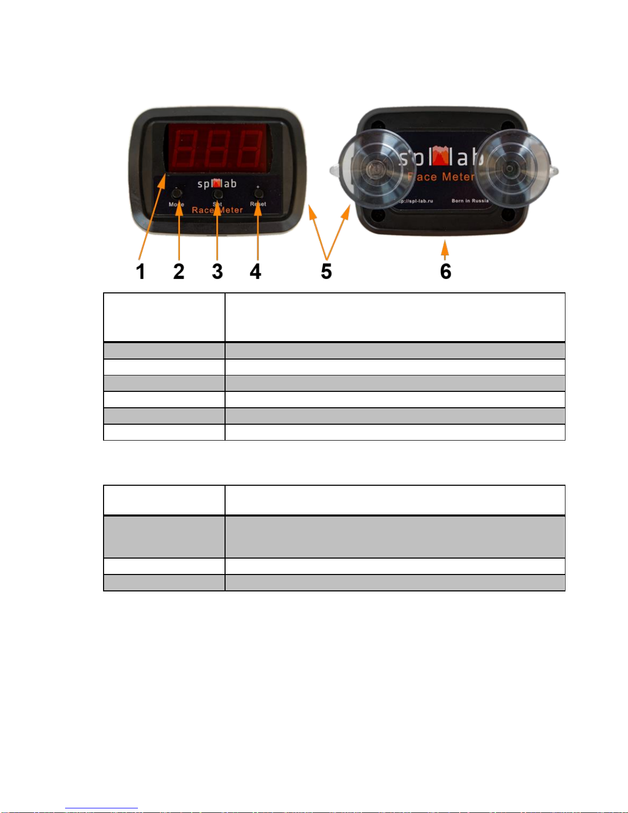
Identifying the functional parts of the device:
Number of the
element
Description
1
Display
2
Functional button #1
3
Functional button #2
4
Functional button #3
5
Micro-SD slot
6
Mini-USB slot for power supply and updating the internal software
Button assignment
Button
Assignment
Functional button #1
Selecting operation mode (SPD, DST, LP, CFG)
Functional button #2
Accessing the mode parameter settings
Functional button #3
Resetting measurement results

6
Starting work with the Race Meter
Race Meter device is easy to use and user does not require any additional skills to operate it.
Nevertheless, it is necessary to follow several requirements for receiving accurate measurement
results.
Unpack the device and check the contents of the set. If necessary, insert micro SD into the slot.
Connect the USB cable to the device. Connect the other end of the cable to the USB adapter of
the cigarette lighter or to a PC, tablet or smartphone. Use only quality cables and adapters, which
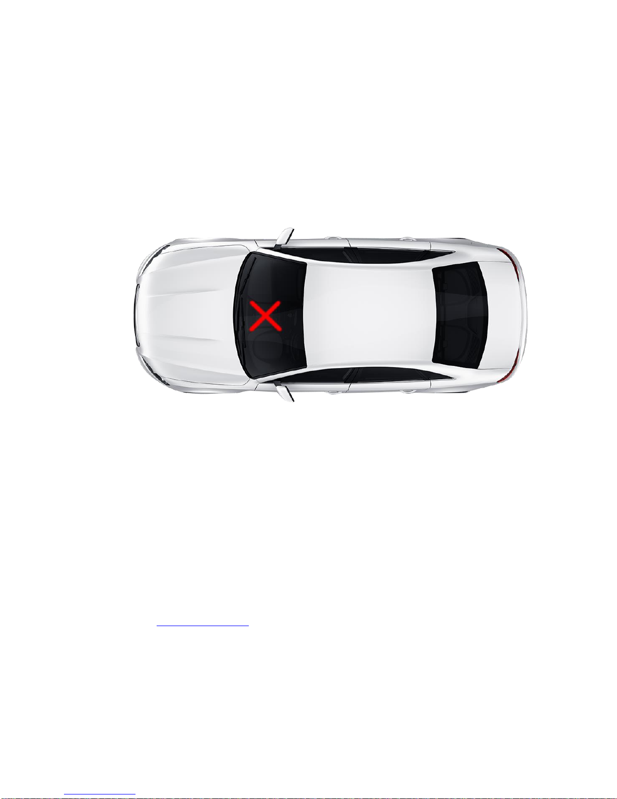
are included with the delivery set or their equivalents. Using suction cups at the back of the
device’s enclosure, attach the Race Meter in the middle of the windshield as illustrated in the
picture.
If the measurements are taken in a vehicle other than a car, when installing the device, consider
that for consistent GPS/GLONASS reception, the backside of the device should be directed
upwards. For improving the quality of reception, avoid placing other electronic devices (radar
detection device, tablet PC, smartphone) close to the area where the Race Meter is attached.
If the device was not used for a long time or was removed to a considerable distance, it is
necessary to reset all settings and GPS/GLONASS data. For doing so, before connecting the
device, press Functional button #2 and wait until the screen shows “rES”.
The Race Meter has a system of self-testing that starts to work each time the device is switched
on and during the time it operates. If after starting the device, indication BAt appears onscreen, it
means that the internal battery should be replaced. For replacing it, take the backside of the
enclosure off and replace the battery. Use CR1225 Batteries ONLY. If while starting or
operating the device, you see Er onscreen or if any other questions, please get in touch with
Support at www.spllabusa.com.
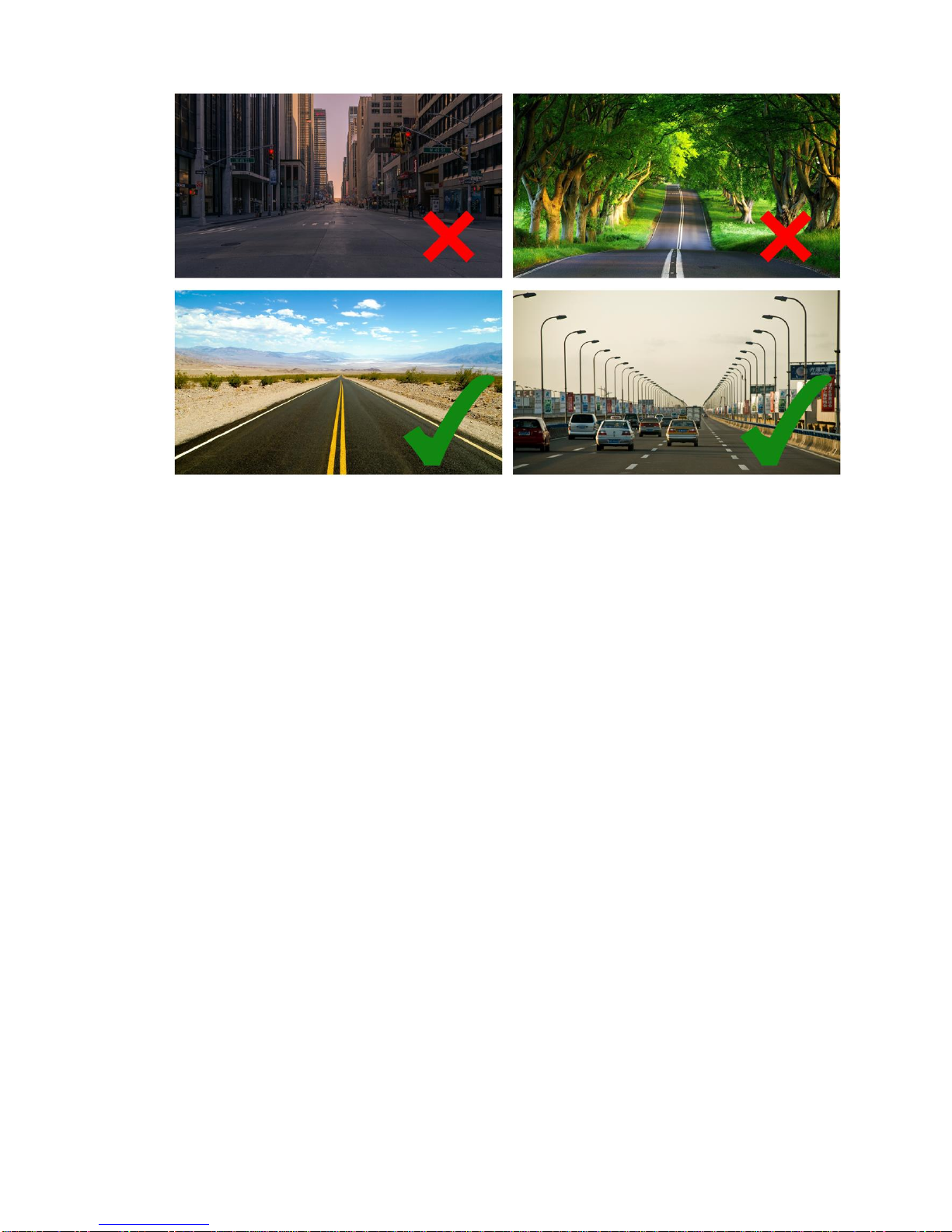
When choosing a place and a road for taking measurements, consider that buildings and trees
next to the road makes reception of GPS/GLONASS worse and can distort the measurement
results. Choose an open space without trees, buildings, mountains, hills, etc. At the picture
below, the typical examples are shown.

7
After starting and self-testing, the device displays blinking writing GPS, which means that
GPS/GLONASS satellites are being searched. If the device was not used for a long time or was
removed to a considerable distance, or all settings were reset, the cold start is applied, which may
take up to several minutes. After the cold start, it is recommended to give the device several
minutes for finding more satellites before starting work. When the device is searching for
satellites, you can make settings for all modes. On following launches, satellite contact will be
established much faster.

8
Device Operation Modes
The Race Meter device has several modes intended for different tasks. After switching on, the
SPD mode will be enabled automatically. For switching between modes, use Functional
button #1. Before the mode is enabled, its name will be displayed onscreen. The list of modes
are given below:
SPD mode for measuring acceleration or deceleration time between specified speed
values. Time and distance travelled are being displayed.
LP mode for measuring lap time. Time and maximum speed are being displayed.
DST mode for measuring time required for covering the specified distance (1/8, 1/4 or
1/2 mile). Time and output speed are being displayed.
LOG mode for enabling and disabling telemetry logging and SD card cleanup.
CFG mode for configuring main operation parameters of the device
USB mode for transmitting the logged data from SD card to a PC, tablet or smartphone.

9
SPD mode for measuring acceleration or deceleration
SPD mode is intended for measuring acceleration or deceleration time between specified speed
values. In addition, the travelled distance is being displayed.
Setting mode parameters
Access the parameter setting mode by pressing Functional button #2. Until setup is
complete, values onscreen will be blinking rapidly. The first defined parameter, “SP1”,
will be displayed.
Press Functional button #2 one more time and the predefined value of starting speed
will be displayed.
Using Functional buttons #1 and 3, set the index value of the starting speed and press
Functional buttons #2 for confirming the input.
In a similar fashion, set the index value, “SP2”, for final speed.
After the last parameter is set and the Functional button #2 is pressed, the settings mode
will be exited and the name of the SPD mode will be displayed.
Taking measurements
After the mode is enabled, the device will be displaying the current speed and will be waiting for
the vehicle to reach a predefined speed, SP1. If SP1 is equal to zero, the device will be waiting
for the vehicle to pull away.
If you would like to use the device as a high-precision digital speedometer, set unreachable SP1
value, for example, 200 or 300 km/h (124 or 186 mph).
When the starting speed is achieved, the device will display GO for a short moment and start the
countdown of measurement time. If the speed drops below 5 km/h (3.1 mph), the measurement
will be stopped automatically.
After the final speed is achieved, the device will display results in a recurring manner and the
values will be blinking:
t -time in seconds with maximum precision up to two decimals
d –distance travelled in meters/feet
r –distance travelled in kilometres/miles if it is above 999 meters/feet.
For returning or resetting the current measurement, press Functional button #3.

10
LP mode for measuring lap time
LP mode is intended for measuring the time required for the vehicle to return to the starting point
(lap time) and the maximum speed achieved.
Taking measurements
After the mode is enabled, the device will be displaying the current speed and will be waiting for
the vehicle to stop. After the speed drops to zero, the Race Meter will be waiting for the vehicle
to pull away.
After movement begins, the device will display GO for a short moment and start the countdown
of measurement time. If the speed drops below 5 km/h (3.1 mph), the measurement will be
stopped automatically.
After the starting point of the route is reached, the device will display results in a recurring
manner and the values will be blinking:
t -time in seconds with maximum precision up to two decimals
u –maximum speed
For returning or resetting the current measurement, press Functional button #3.
Inhaltsverzeichnis
Andere SPL-Laboratory Messgerät Handbücher

SPL-Laboratory
SPL-Laboratory Mini Bass Meter 2016 Bedienungsanleitung

SPL-Laboratory
SPL-Laboratory LCD Bass Meter SE Bedienungsanleitung

SPL-Laboratory
SPL-Laboratory Next-LCD 2015 Bedienungsanleitung

SPL-Laboratory
SPL-Laboratory Smart Voltmeter 2014 Bedienungsanleitung

SPL-Laboratory
SPL-Laboratory Mini Bass Meter 2018 Bedienungsanleitung

SPL-Laboratory
SPL-Laboratory Wireless Bass Meter Bedienungsanleitung