
Tactical TFM VT-222 Bedienungsanleitung

TFM VT-222 Vortex Flowmeter User Manual
TFM VT-222 Multi Variable Vortex Flow Meter
Goes with ModBus
QUICK User Manual
Take 5, Inc.
1335 Dayton Street Unit A
Salinas, CA 93901
Dave@TacticalFlowMeter.com
Call 831-244-8080
QR Code for Website with Videos. Open Video tab and watch the first video for
simple user configuration instructions
TFM VT-222 Vortex Flowmeter Quick Manual Rev 10f page 1 of 30
TFM VT-222 Vortex Flowmeter User Manual
Table Of Contents
Technical Support 3
Electronics Specifications 3
Hardware 4
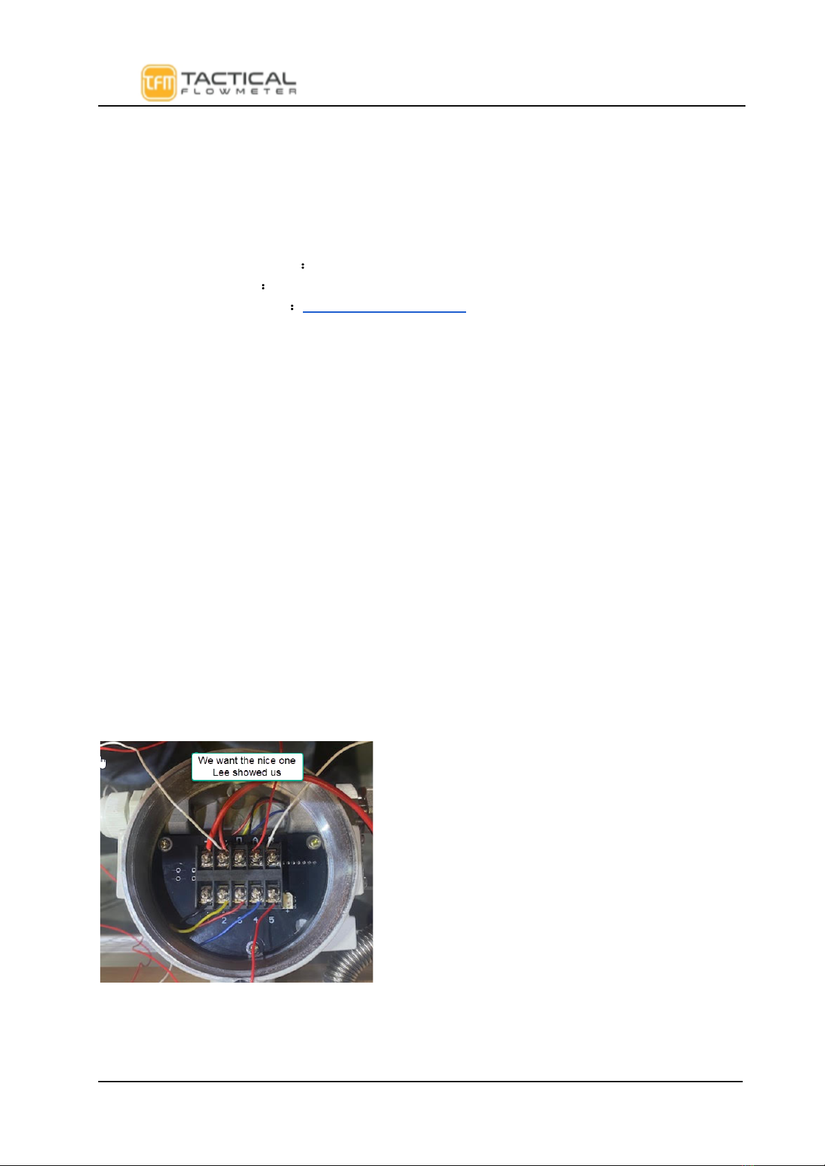
Terminal Board Wiring 4
4-20mA output HART External Pressure
Lee: Do we have new photos for the connector board with the nice labeled connections? 5
Pulse Output+ External Pressure and Temperature sensors 5
Sensor Interface 5
Vortex Sensor 5
Pressure Sensor 6
Temperature Sensor 6
Vortex Dimensions: 7
LCD Display 7
Three-line display mode 8
Two-Line Display: 8
Local Adjustment:.. Probably do not need this below…. 9
Data Entry: 10
Pipe diameter 12
Pressure Unit 12
Flow correction factor 12
Test modes 12
Traffic test mode 12
Frequency test mode 12
Current test mode 12
Loop current calibration 13
Custom units 13
Basic Functions No Password Required 14
Password Protected Functions 15
1 Protocol Overview 22
1.1 Serial Communication Parameters 22
1.3 Communication Interface Functions Format 22
1.3.2 Function 04(Read Input Register) example 23
1.3.3 Function Code 16(Write Holding Registers) example 23
2 Register Description 23
2.1 Input Registers Table (Variables) 23
TFM VT-222 Vortex Flowmeter Quick Manual Rev 10f page 2 of 30
TFM VT-222 Vortex Flowmeter User Manual
H86CT1 Product Manual
Technical Support
TacticalFlowMeter VT-222 Vortex flowmeters utilize piezo sensors to detect the Vortex Shedding
Frequency. We integrate internal Pressure and Temperature sensors to provide for full multivariable
operation. Please read this manual carefully before using the meter. If you have any questions, please
do not hesitate to contact us.
Company:Take 5, Inc. dba TacticalFlowMeter.Com
Tel:831-244-8080 x1 Sales, x2 Support
Website:www.TacticalFlowMeter.com
Electronics Specifications
Power Supply: 12-32VDC
Operating Temperature: -20°C to 70°C(with LCD -40°C to 85°C(without LCD)
Output: 4-20mA output
Configuration: Flow mode, Flow unit, Range (Qmax), Density, Temperature, etc.
Alarm: Low alarm outputs 3.8 mA & high alarm can outputK-Factor linearity: The VT-222 provides 2 to 5
points of K-Factor linearity correction.
Local adjustments: Setting range and PV units, Density, Flow mode, damping, high alarm percent, low alarm
percent and data recovery etc.
LCD display: Line 1 shows the instantaneous flow. Line 2 shows the totalized flow. Line 3 can display the
percentage, output current, temperature, pressure, density and more combinations easily selected by the user.
Multivariable Operation:The VT-222 supports real-time temperature and pressure compensation for gas, and
utilizes the international standard for the steam and density tables for temperature and pressure compensation as well
for superheated steam with pressure compensation or temperature compensation for saturated steam.
Temperature trim: High trim and low trim .
Pressure trim: High trim and low trim .
The VT-222 provides power-down protection and flow totalizer value storage functions.
Hardware
Terminal Board Wiring
The terminal board is used for connection to the external power supply, output pulse, the external
pressure sensor and temperature sensor.
The following are common wiring methods.
TFM VT-222 Vortex Flowmeter Quick Manual Rev 10f page 3 of 30

TFM VT-222 Vortex Flowmeter User Manual
4-20mA output HART External Pressure
Pulse Output External Pressure and Temperature sensors
Sensor Interface
Vortex Sensor
The 2-Pin green XT terminal is used for connecting the vortex piezo sensor that has no polarity.
Note: The main circuit board must be properly safety grounded
according to NEMA safety standards
TFM VT-222 Vortex Flowmeter Quick Manual Rev 10f page 4 of 30

TFM VT-222 Vortex Flowmeter User Manual
Pressure Sensor
Use the XF3 socket to connect the pressure sensor (pressure sensor must be a bridge type
sensor). I+ and I- are the power supply, A + and A- are the sensor signal outputs.
The bridge impedance of the pressure sensor must be between 3 to 6000 ohms. The supply current for
the pressure sensor is about 0.3 mA. As long as the sensor output does not exceed [email protected], you
may use an external sensor of your choice.
Socket XF3 defined as follows:
Temperature Sensor
Socket XF5 supports Pt1000 and Pt100, two-wire connection.
TFM VT-222 Vortex Flowmeter Quick Manual Rev 10f page 5 of 30

TFM VT-222 Vortex Flowmeter User Manual
Note: The main circuit board must be properly safety grounded
according to NEMA safety standards
Vortex Dimensions:
LCD Display
The LCD display features a 128 x 64 dot matrix full graphics display, allowing for convenient display modes to suit
specific needs. The instrument supports two display modes:
TFM VT-222 Vortex Flowmeter Quick Manual Rev 10f page 6 of 30

TFM VT-222 Vortex Flowmeter User Manual
Three-line display mode
Line 1 displays the Instantaneous flow.
Line 2 displays the totalized flow.
Line 3 displays frequency, pressure,fluid temperature, density,
current, or percentage.
Notes:
►When using the onboard pressure sensor, and the pressure signal has a fault condition, the
corresponding pressure value will be replaced with the set pressure value and it will flash.
► When using the onboard temperature sensor, and the temperature signal has a fault condition, the
corresponding temperature value will be replaced with the set temperature value and it will flash as well.
► When the flow mode is Sat_Steam(P), indicating it is in saturated steam pressure compensation, the
temperature value will display as " ", which indicates the measurement of the temperature sensor is not
enabled.
►When the flow mode is Sat_Steam(T), indicating it is in saturated steam temperature compensation,
the pressure value will display as " ", which indicates the measurement of the pressure sensor is not
enabled.
Note: Long Press KEY-D to change the third line display variable(s) to one of the
following: Note this meter can accurately indicate the DENSITY!
Two-Line Display:
Bar Graph 0- 100% Full Scale
Line 1 displays the Instantaneous flow.
Line 2 displays the totalized flow.
TFM VT-222 Vortex Flowmeter Quick Manual Rev 10f page 7 of 30
TFM VT-222 Vortex Flowmeter User Manual
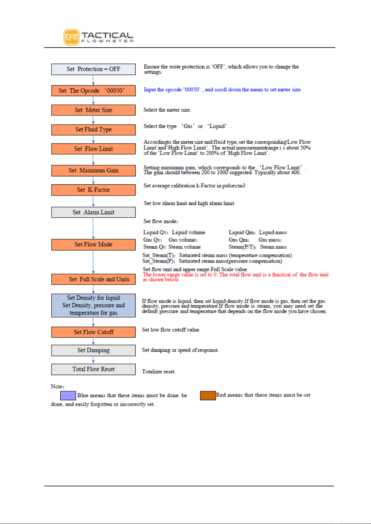
Local Adjustment:.. Probably do not need this below….
TFM VT-222 Vortex Flowmeter Quick Manual Rev 10f page 8 of 30
TFM VT-222 Vortex Flowmeter User Manual
Data Entry:
Enter or Exit Menu Mode
Enter Menu Mode
In the operating mode, press the "E" key to Enter the menu mode (data entry).
Exit Menu Mode
In the menu mode, press the "E" key to Exit the menu mode and Enter the operating mode.
Data Entry Method
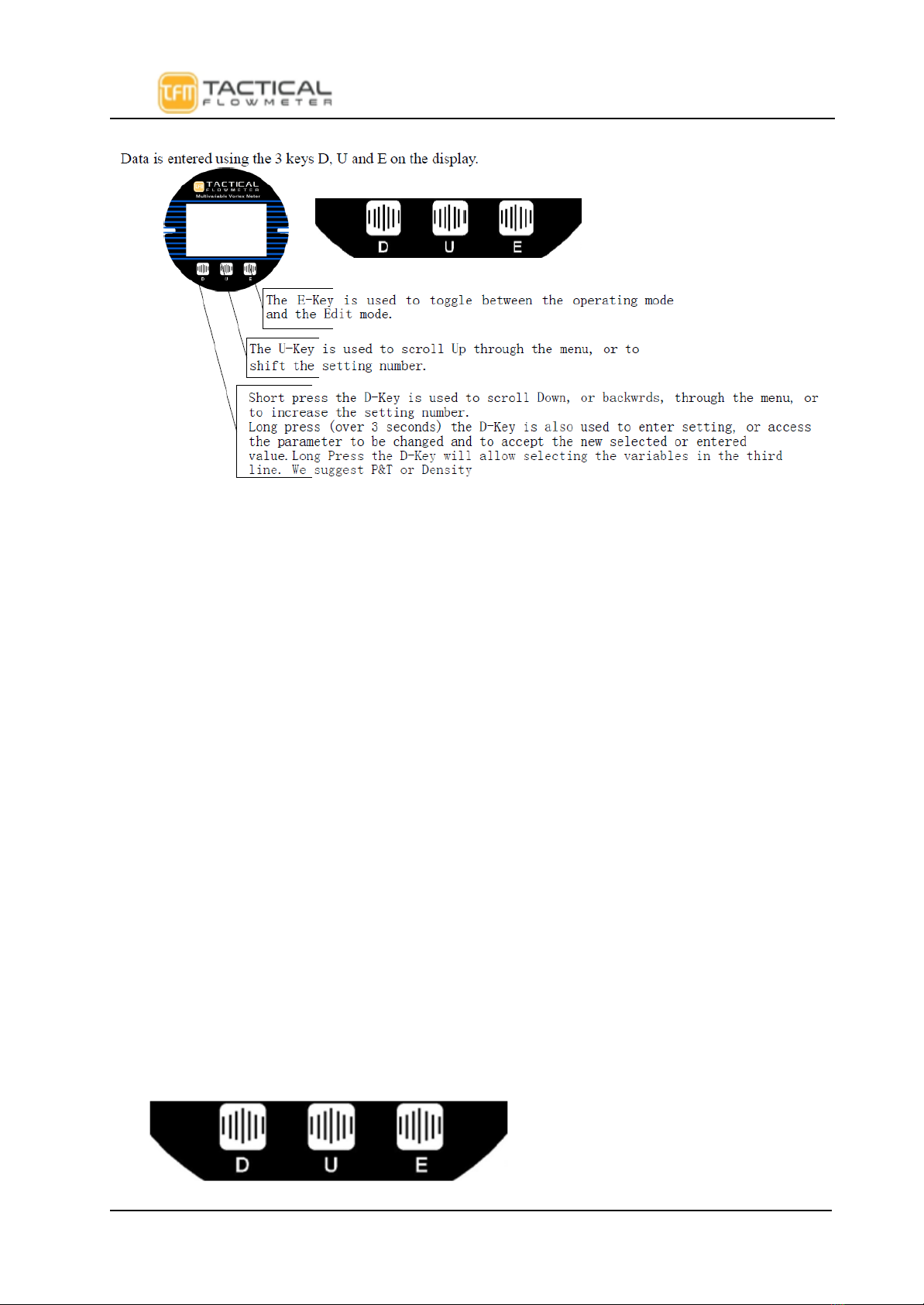
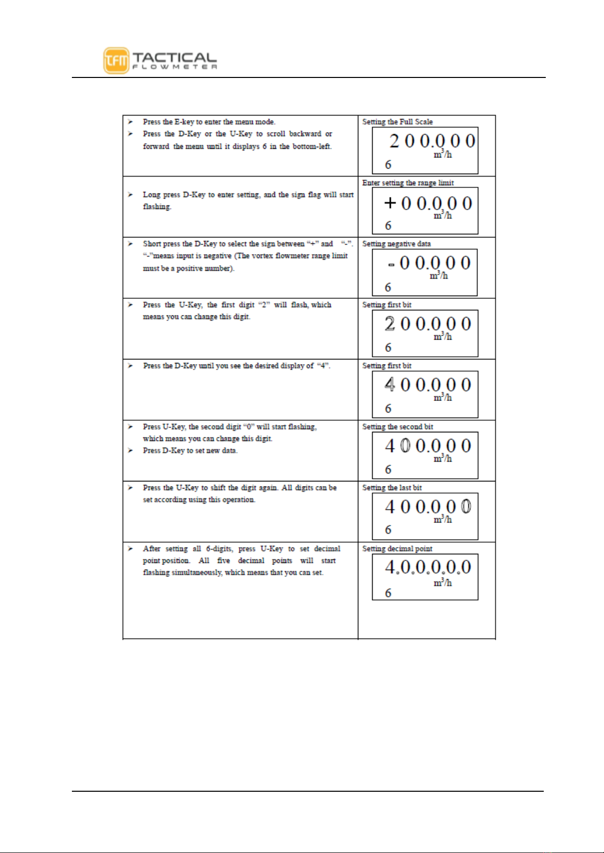
There are two ways to set parameters, one is using the "Keypad Method" with the3 button interface on the
electronics and the other way is to use ModBus to set the parameters. To make it easier be sure to watch the videos
on the website that demonstrates the methods clearly.
‘Keypad’ Method
1. Long press the D-Key to enter the setting, and the sign flag will start flashing.
2. Short press the D-Key to select the sign.
3. Press the U-Key to shift the setting number. The number bit will start flashing, which means that
you can set. Press D-Key to increase the setting number.
4. Press the U-Key to shift the setting number again. All digits can be set using the same method.
5. After setting all 6-digits, press U-Key to set the decimal point position. All five decimal points will flash
simultaneously, indicating they can be set. Short press D-Key to change the decimal point position.
6. After completing data entry, you can long press D-Key to save the parameters. Or Press E Key to abort and
exit. The D and E Keys are important to select based on your needs. Long hold the D-Key to save your
changes.
For example, On the next pages we show changing the Full Scale from 200, the new input range limit
of 400. Setting the range limit, Full Scale, is important for driving the 4-20 mA and Frequency
Outputs.
●Long press D-Key to enter settings, and the menu options will start flashing.
●Short press D-Key or S-Key to scroll backward or forward in the menu.
●Long press D-Key to access, and then save, the parameter.
Refer to the key names below.:
TFM VT-222 Vortex Flowmeter Quick Manual Rev 10f page 9 of 30
TFM VT-222 Vortex Flowmeter User Manual
TFM VT-222 Vortex Flowmeter Quick Manual Rev 10f page 10 of 30
Inhaltsverzeichnis


