TFT FLEX Series Programmierhandbuch

©Copyright Task Force Tips LLC 2023 1 LIY-220 August 21, 2023 Rev00
TASK FORCE TIPS LLC
MADE IN USA · tft.com
3701 Innovation Way, Valparaiso, IN 46383-9327 USA
800-348-2686 · 219-462-6161 · Fax 219-464-7155
G-Force
INSTRUCTION FOR INSTALLATION, OPERATION, AND MAINTENANCE
FLEX™ MONITOR
SERIES
DANGER
Understand manual before use. Operation of this device without understanding the manual and
receiving proper training is a misuse of this equipment. Obtain safety information at tft.com/
serial-number.
This equipment is intended for use by trained and qualified emergency services personnel for
firefighting. All personnel using this equipment shall have completed a course of education
approved by the Authority Having Jurisdiction (AHJ).
This instruction manual is intended to familiarize firefighters and maintenance personnel with the
operation, servicing, and safety procedures associated with this product. This manual should be
kept available to all operating and maintenance personnel.
(see section 3.2) for Flow/Pressure Operations Envelope
FLEX
WITH TILLER
FLEX
WITH CRANK
FLEX RC

©Copyright Task Force Tips LLC 2023 2 LIY-220 August 21, 2023 Rev00
The member companies of FEMSA that provide emergency
response equipment and services want responders to know and
understand the following:
1. Firefighting and Emergency Response are inherently
dangerous activities requiring proper training in their hazards
and the use of extreme caution at all times.
2. IT IS YOUR RESPONSIBILITY to read and understand
any user’s instructions, including purpose and limitations,
provided with any piece of equipment you may be called on
to use.
3. IT IS YOUR RESPONSIBILITY to know that you have been
properly trained in Firefighting and/or Emergency Response
and in the use, precautions, and care of any equipment you
may be called upon to use.
4. IT IS YOUR RESPONSIBILITY to be in proper physical
condition and to maintain the personal skill level required to
operate any equipment you may be called upon to use.
5. IT IS YOUR RESPONSIBILITY to know that your equipment is
in operable condition and has been maintained in accordance
with the manufacturer’s instructions.
6. Failure to follow these guidelines may result in death, burns or
other severe injury.
Fire and Emergency Manufacturers and Service Association, Inc.
PO Box 147, Lynnfield, MA 01940 • www.FEMSA.org
© 2020 FEMSA. All Rights Reserved.
PERSONAL RESPONSIBILITY CODE
DANGER

©Copyright Task Force Tips LLC 2023 3 LIY-220 August 21, 2023 Rev00
TABLE OF CONTENTS
1.0 MEANING OF SAFETY SIGNAL WORDS
2.0 SAFETY
3.0 GENERAL INFORMATION
3.1 MECHANICAL SPECIFICATIONS
3.2 OPERATING ENVELOPE
3.3 USE WITH SALT WATER
3.4 VARIOUS MODELS AND TERMS
3.5 INLETS AND OUTLETS
3.5.1 OUTLET ADAPTER
3.6 OVERALL DIMENSIONS
4.0 INSTALLATION
4.1 ELECTRICAL INSTALLATION
4.2 STRUCTURAL REQUIREMENTS
4.3 TWO-PIECE ROTATIONAL LOCK INSTALLATION
4.4 CABLE ROUTING FOR EXTEND-A-GUN
4.5 FLEX INSTALLATION ON VUM
4.6 HORIZONTAL ROTATION TRAVEL STOPS
4.7 INSTALLING THE HORIZONTAL TRAVEL STOPS
4.8 ELEVATION TRAVEL STOPS
4.9 NOZZLE INSTALLATION
4.10 PRESSURE GAUGE PORT
4.11 TILLER HANDLE INSTALLATION
4.12 DRAINING RESIDUAL WATER
5.0 OPERATING INSTRUCTIONS
5.1 HANDWHEEL HORIZONTAL ROTATIONAL CONTROL
5.2 HANDWHEEL ELEVATION CONTROL
5.3 TILLER BAR CONTROL
5.4 RECOMMENDED PARK POSITION
5.5 OVERRIDE KNOBS
6.0 FLOW CHARACTERISTICS
6.1 YST-4NN STACKED TIPS FLOW AND REACH
6.2 MST-4NJ STACKED TIPS FLOW AND REACH
6.3 EFFECTS OF ELEVATION AND WIND ON STREAM REACH
6.4 AUTOMATIC MASTERSTREAM NOZZLES
6.5 FRICTION LOSS
6.6 STREAM STRAIGHTENERS
6.6.1 STREAM STRAIGHTENERS WITH STACKED TIPS
6.6.2 STREAM STRAIGHTENERS WITH FOG NOZZLES
7.0 WARRANTY
8.0 MAINTENANCE
8.1 SERVICE TESTING
8.2 LUBRICATION
8.3 TROUBLESHOOTING
8.4 REPAIR
9.0 EXPLODED VIEWS AND PARTS LISTS
10.0 OPERATION AND INSPECTION CHECKLIST
©Copyright Task Force Tips LLC 2023 4 LIY-220 August 21, 2023 Rev00
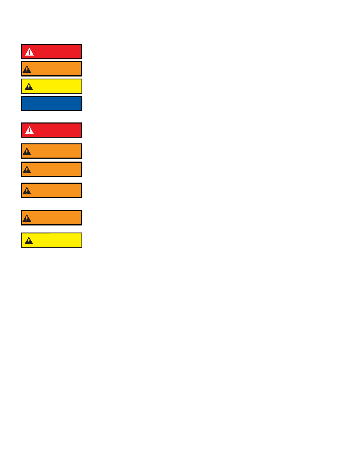
1.0 MEANING OF SAFETY SIGNAL WORDS
A safety related message is identified by a safety alert symbol and a signal word to indicate the level of risk involved with a particular
hazard. Per ANSI Z535.6, the definitions of the four signal words are as follows:
2.0 SAFETY
DANGER
DANGER indicates a hazardous situation which, if not avoided, will result in death or serious injury.
WARNING
WARNING indicates a hazardous situation which, if not avoided, could result in death or serious
injury.
CAUTION CAUTION indicates a potentially hazardous situation which, if not avoided, could result in minor
or moderate injury.
NOTICE
NOTICE is used to address practices not related to physical injury.
DANGER
An inadequate supply of pressure and/or flow will cause an ineffective stream and can result
in injury or death. Choose operating conditions to deliver adequate fire suppression. See flow
graphs.
WARNING
Injury or damage can occur from an inadequately supported monitor. The mounting must be
capable of supporting the nozzle reaction force which can be as high as 1500 lbs.
WARNING
The stream exiting a nozzle is very powerful and capable of causing injury and property damage.
Make sure the nozzle is securely attached and pointing in a safe direction before water is turned on.
Do not direct water stream to cause injury or damage to persons or property.
WARNING
Equipment may be damaged if frozen while containing significant amounts of water. Such damage
may be difficult to detect visually. Subsequent pressurization can lead to injury or death. Any time
the equipment is subject to possible damage due to freezing, it must be tested and approved for
use by qualified personnel before being considered safe for use.
WARNING
On many vehicle installations, the monitor is the highest point on the apparatus. Damage or injury
could occur if there is not sufficient clearance to safely pass under doors or overhead obstructions.
Always check stowed position of the monitor before moving.
CAUTION The electric drives are current limited but may still produce enough force to cause injury. To avoid
injury from moving equipment:
• Be aware that equipment may be remotely operated
• Keep hands and fingers away from pinch points
• Never operate the manual override while electric controls are in operation

©Copyright Task Force Tips LLC 2023 5 LIY-220 August 21, 2023 Rev00
3.0 GENERAL INFORMATION
FLEX is a mounted master stream monitor/ water cannon with flow ranges from 1250 GPM (4750 LPM) to 2000 GPM (7600 LPM).
The unique design minimizes curves in the waterway, lowering friction loss, resulting in a higher-quality, further reaching water stream.
Paired with the FLEX Ops app, the monitor is customizable and simple to install and program.
3.1 MECHANICAL SPECIFICATIONS
.0
Table 3.1
MANUAL ELECTRIC
US METRIC US METRIC
Weight* 33 to 39 lbs 15 to 18 kg 42 to 47 lbs 19 to 21 kg
Minimum Flow Area (4” Inlet x 3.5” Outlet) 9.6 in261.9 cm29.6 in261.9 cm2
Minimum Flow Area (3” Inlet x 2.5” Outlet) 4.9 in231.6 cm24.9 in231.6 cm2
Maximum Operating Pressure 200 psi 14 bar 200 psi 14 bar
Nominal Operating Voltage n/a n/a 12 or 24 VDC (auto sense)
Maximum Voltage n/a n/a 32 VDC
Operating Temperature Range of Fluid 33°F to 120°F / 1°C to 50°C
Storage Temperature Range -40 to 150°F / -40 to 65°C
Maximum Torque (Elevation)
n/a
80 ft-lbs 110 N·m
Maximum Torque (Horizontal) 60 ft-lbs 80 N·m
Speed (Elevation) 6 deg/sec
Speed (Horizontal) 12 deg/sec
Speed at Maximum Load (Elevation) 5 deg/sec
Speed at Maximum Load (Horizontal) 10 deg/sec
Materials ANSI A356.0-T6 Aluminum, Stainless, Nylon
* Weight varies by model, see website listing for specific model weight.

©Copyright Task Force Tips LLC 2023 6 LIY-220 August 21, 2023 Rev00
3.2 OPERATING ENVELOPE
Figure 3.2A
Figure 3.2B
WARNING
Damage or injury could result from operating the monitor beyond the safe operating envelope. Do
not operate the monitor outside the envelope in the following graph(s).
Monitor Inlet Pressure (bar)
3.5” FLEX Monitor Operating Envelope
0 1000 2000 3000 4000 5000 6000
0
2
4
6
8
10
12
14
16
0
25
50
75
100
125
150
175
200
225
250
0 200 400 600 800 1000 1200 1400 1600
Flow (lpm)
Monitor Inlet Pressure (bar)
Monitor Inlet Pressure (psi)
Flow (gpm)
Nozzle A
Inlet Pressure
Nozzle B
Inlet Pressure Nozzle C
Inlet Pressure
Maximum Monitor
Inlet Pressure
Maximum Nozzle
Inlet Pressure
Nozzle A Ňows 500 gpm (1900 lpm) at 100 psi (6.9 bar), K factor = 50
Nozzle B Ňows 1000 gpm (3800 lpm) at 100 psi (6.9 bar), K factor = 100
Nozzle C Ňows 1500 gpm (5700 lpm) at 100 psi (6.9 bar), K factor = 150
Monitor Loss
2.5” FLEX Monitor Operating Envelope

©Copyright Task Force Tips LLC 2023 7 LIY-220 August 21, 2023 Rev00
3.3 USE WITH SALT WATER
Use with salt water is permissible provided the equipment is thoroughly cleaned with fresh water after each use. The service life of the
equipment may be shortened due to the effects of corrosion, and is not covered under warranty.
3.4 VARIOUS MODELS AND TERMS
rm model has a smaller swing radius and has horizontal travel stops factory installed at 90° left and right (180° total).trol
Figure 3.4A
Manual Model with Crank
Figure 3.4B
Manual Model with Tiller
OUTLET
HORIZONTAL
ROTATION
HANDCRANK
ELEVATION
HANDCRANK
HORIZONTAL ROTATION
TRAVEL STOPS
PORT FOR
PRESSURE GAGE
INLET
GEARBOX WITH
VERTICAL STOPS
VERTICAL
LOCKING
KNOB
HORIZONTAL
LOCKING
KNOB
TILLER HANDLE

©Copyright Task Force Tips LLC 2023 8 LIY-220 August 21, 2023 Rev00
Figure 3.4C
RC Model
3.5 INLETS AND OUTLETS
There is a wide variety of inlet and outlet options for the FLEX monitor. The overall height and weight of the monitor may differ slightly
based on the inlet and outlet configuration. See finished good drawing on the website listing for specific model dimensions.
3.5.1 OUTLET ADAPTER
FLEX monitors with 2.5" threaded outlets may easily converted to 3.5"NH threads by tightening four screws surrounding the outlet, then
unscrewing the 2.5" threaded outlet and O-ring using a strap wrench.
MANUAL OVERRIDE KNOB
FOR ELEVATION
MANUAL OVERRIDE KNOB
FOR HORIZONTAL ROTATION
ELEVATION GEAR MOTOR
HORIZONTAL ROTATION
GEAR MOTOR

©Copyright Task Force Tips LLC 2023 9 LIY-220 August 21, 2023 Rev00
3.6 OVERALL DIMENSIONS
Figure 3.6A
Manual Model with Crank
(Shown with 4” ANSI 150 inlet, see finished good drawing on the website for specific model dimensions)
Figure 3.6B
RC Model
(Shown with 4” ANSI 150 inlet, see finished good drawing on the website for specific model dimensions)
14.86"
[377 mm]
18.38"
[467 mm]
7.93"
[201 mm]
10.45"
[265 mm]
11.94"
[303 mm]
45°
90°
4.31"
[109 mm]
6.11"
[155 mm]
10.42"
[265 mm]
8.45"
[215 mm]
SWING
360°
CONTINUOUS
16.66"
[423 mm]
5.05"
[128 mm]
10.45"
[265 mm]
15.50"
[394 mm]
45°
120°
10.55"
[268 mm]
4.55"
[116 mm]
6.00"
[153 mm]
6.00"
[153 mm]
SWING
225°
RIGHT
225°
LEFT

©Copyright Task Force Tips LLC 2023 10 LIY-220 August 21, 2023 Rev00
Figure 3.6C
Manual Model with Tiller
(Shown with 4” ANSI 150 inlet, see finished good drawing on the website for specific model dimensions)
17.30"
[439 mm]
15.70"
[399 mm]
45°
120°
11.94"
[303 mm]
6.85"
[174 mm]
10.45"
[265 mm]
9.24"
[235 mm]
4.59"
[117 mm]
13.83"
[351 mm]
10.137"
[257 mm]
SWING
360°
CONTINUOUS
Inhaltsverzeichnis
Andere TFT Messgerät Handbücher


