tornos DECO 13a Bedienungsanleitung

QUICK REFERENCE
DECO 13a
en 300417
Printed in Switzerland Copyright 1999−2008

Δ
WARNING !
Before handling the machine, read first the
information contained in the instructions
entitled “SAFETY REGULATIONS”.
These instructions are based on the information available at the moment of
their publication. Although the very best has been done to make them as
comprehensive and precise as possible they do not purport to cover all
details of the hardware and software nor to anticipate every contingency.
TORNOS S.A. give no guarantee nor assume any responsibility for the
exactitude and the sufficiency of the information contained in this document.
The contents of the instructions remain the property of TORNOS S.A.,who
reserve the right to modify, complete or correct them at any time.
The original language of the instructions to be referred to is French.
The hazards of misinterpreting the instructions can be considerably reduced
by following the training courses organized and offered by TORNOS S.A.
TORNOS SA − CH−2740 MOUTIER − http://www.tornos.ch

QUICK REFERENCE − DECO 13A
en 300417 − 04/08 3
CONTENTS
1. GENERAL 5. . . . . . . . . . . . . . . . . . . . . . . . . . . . . . . . . . . . . . .
1.1 ZERO DATUM SYMBOLS 5. . . . . . . . . . . . . . . . . . . . . . . . . .
1.2 AXIS TRAVEL 5. . . . . . . . . . . . . . . . . . . . . . . . . . . . . . . . . . . .
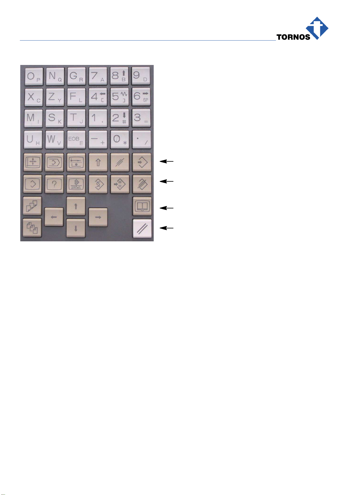
1.3 NC KEYBOARD 6. . . . . . . . . . . . . . . . . . . . . . . . . . . . . . . . . .
1.4 CONTROL PANEL 7. . . . . . . . . . . . . . . . . . . . . . . . . . . . . . . .
1.5 CONTROL PANEL DESCRIPTION 8. . . . . . . . . . . . . . . . . .
1.6 G−FUNCTIONS (PREPARATORY) 9. . . . . . . . . . . . . . . . . .
1.7 FUNCTION GROUPS 13. . . . . . . . . . . . . . . . . . . . . . . . . . . . . .
1.8 G9XX MACROS 14. . . . . . . . . . . . . . . . . . . . . . . . . . . . . . . . . .
1.9 GLOBAL PART VARIABLES 15. . . . . . . . . . . . . . . . . . . . . . . .
1.10 GLOBAL PROGRAM VARIABLES 16. . . . . . . . . . . . . . . . . . .
1.11 M−FUNCTIONS 17. . . . . . . . . . . . . . . . . . . . . . . . . . . . . . . . . . .
1.12 T−FUNCTIONS 26. . . . . . . . . . . . . . . . . . . . . . . . . . . . . . . . . . .
1.13 KINEMATICS 28. . . . . . . . . . . . . . . . . . . . . . . . . . . . . . . . . . . . .
1.14 AXIS NO. 29. . . . . . . . . . . . . . . . . . . . . . . . . . . . . . . . . . . . . . . .
2. OPERATE MACHINE FUNCTIONS 30. . . . . . . . . . . . . . . . . .
2.1 REFERENCING 30. . . . . . . . . . . . . . . . . . . . . . . . . . . . . . . . . .
2.1.1 Reference All Axes 30. . . . . . . . . . . . . . . . . . . . . . . . . . . . . . . . . . . . . . . . .
2.1.2 Reference Axis by Axis: 31. . . . . . . . . . . . . . . . . . . . . . . . . . . . . . . . . . . . .
2.2 MANUAL DATA INPUT (MDI) OPERATION 32. . . . . . . . . . .
2.3 JOG AN AXIS 33. . . . . . . . . . . . . . . . . . . . . . . . . . . . . . . . . . . .
2.4 INCREMENT AN AXIS 34. . . . . . . . . . . . . . . . . . . . . . . . . . . . .
2.5 AUTO MODE 35. . . . . . . . . . . . . . . . . . . . . . . . . . . . . . . . . . . . .
2.6 RUN A PROGRAM AT 5% FEEDRATE FORWARD 36. . . .
2.7 EDIT TOOL WEAR OFFSET 36. . . . . . . . . . . . . . . . . . . . . . . .
2.8 DISABLE X3−Z3−S3 & X4−Y4−Z4 AXIS 37. . . . . . . . . . . . . .

QUICK REFERENCE − DECO 13A
en 300417 − 04/08 4
3. DOWNLOAD A PROGRAM 38. . . . . . . . . . . . . . . . . . . . . . . .
3.1 DOWNLOAD A PROGRAM OVER RS−232 CABLE 38. . . .
3.2 DOWNLOADING A PROGRAM OVER RS−232 39. . . . . . .
3.3 DOWNLOAD A PROGRAM WITH MEMORY CARD 41. . . .
3.4 DOWNLOADING A PROGRAM WITH MEMORY CARD: 42
3.5 RESTORE OFFSETS 44. . . . . . . . . . . . . . . . . . . . . . . . . . . . . .
4. DRIVE 45. . . . . . . . . . . . . . . . . . . . . . . . . . . . . . . . . . . . . . . . . . .
4.1 (307005) S2 DRIVE (X2 / Y2) 46. . . . . . . . . . . . . . . . . . . . . . .
4.2 (307009) S5 DRIVE (X4) 47. . . . . . . . . . . . . . . . . . . . . . . . . . .
4.2.1 Arrangement of the drive belt S5 47. . . . . . . . . . . . . . . . . . . . . . . . . . . . .
4.3 (307010) S6 DRIVE (X1 / Y1) 48. . . . . . . . . . . . . . . . . . . . . . .
4.4 (307011) S3 DRIVE (X3 / Z3) 49. . . . . . . . . . . . . . . . . . . . . . .
4.4.1 Arrangement of the drive belt S3 49. . . . . . . . . . . . . . . . . . . . . . . . . . . . .
5. MISCELLANEOUS 50. . . . . . . . . . . . . . . . . . . . . . . . . . . . . . . .
5.1 BASIC STEPS ON WINDOWS 50. . . . . . . . . . . . . . . . . . . . . .
5.2 COPY ON SAME DISK 50. . . . . . . . . . . . . . . . . . . . . . . . . . . .
5.3 COPY ONTO ANOTHER DISK 50. . . . . . . . . . . . . . . . . . . . . .
5.4 CYCLE THROUGH WINDOWS, ETC. 50. . . . . . . . . . . . . . . .
5.5 COPY / PASTE 50. . . . . . . . . . . . . . . . . . . . . . . . . . . . . . . . . . .
5.6 BASIC TB−DECO STEPS TO SET UP A PROGRAM 51. .
5.7 REFILLING CHUCKING HYDRAULICS 52. . . . . . . . . . . . . .
5.8 MODIFYING TOOL SUPPORT POSITION IN DATABASE 53

QUICK REFERENCE − DECO 13A
en 300417 − 04/08 5
1. GENERAL
1.1 ZERO DATUM SYMBOLS
Machine Zero, fixed point on the machine
Part Zero, moving point on the part face
Tool Zero, reference point for tool geometries
1.2 AXIS TRAVEL
Axes Position
min. Position
max. Reference
point Travel
X1 −14 mm ∅56 mm ∅56 mm ∅35 mm
X2 −14 mm ∅56 mm ∅56 mm ∅35 mm
Y1 −3 mm 155 mm 0 mm 158 mm
Y2 −3 mm 155 mm 0 mm 158 mm
Z1 0 mm 255 mm 0 mm 255 mm
X3 −144 mm ∅230 mm ∅−144 mm ∅187 mm
Z3 −160 mm 0 mm 0 mm 160 mm
X4 −310 mm ∅−6 mm ∅0 mm ∅158 mm
Y4 −1 mm 299 mm 296 mm 300 mm
Z4 0 mm 160 mm 160 mm 160 mm

QUICK REFERENCE − DECO 13A
en 300417 − 04/08 6
1.3 NC KEYBOARD
from 1 to 6
from 7 to 12
13
14
1. POSITION (Display all axes)
2. PROGRAM (Output / Input a program)
3. OFFSET SETTING
4. SHIFT
5. CANCEL
6. INPUT (Enter data)
7. SYSTEM (Access to data)
8. MESSAGE (Display messages / alarms)
9. GRAPH (Display axis position)
10. ALTER (e.g. replace characters)
11. INSERT
12. DELETE
13. HELP
14. RESET

QUICK REFERENCE − DECO 13A
en 300417 − 04/08 7
1.4 CONTROL PANEL
6
12345
F1 F2 F3 F4 F5
789
10 11 12 13 14 15
16 17 18 19
20 21 22 23 24 25

QUICK REFERENCE − DECO 13A
en 300417 − 04/08 8
1.5 CONTROL PANEL DESCRIPTION
1. Emergency Stop
2. NC ON
3. NC OFF
4. Power ON
5. Power OFF
F1−F5 Functions
6. Axis / Channel Selector
7. Mode Selector
8. Axis speed variation
9. Key Selector
10. Axis Feedrate Override (decr.)
11. Axis Feedrate Override (incr.)
12. Spindle Speed Override (decr.)
13. Spindle Speed Override (incr.)
14. Program BACKWARD (inactive)
15. Program FORWARD
16. Open Main Spindle Collet
17. Close Main Spindle Collet
18. Open Pickoff−Spindle Collet
19. Close Pickoff−Spindle Collet
20. CYCLE START
21. Program Stop
22. CYCLE STOP
23. Coolant ON
24. Adjust Coolant
25. Coolant OFF

QUICK REFERENCE − DECO 13A
en 300417 − 04/08 9
1.6 G−FUNCTIONS (PREPARATORY)
Code Function Grp. M/S
G01 Linear interpolation 10 S
G02 Circular interpolation, cw 10 S
G03 Circular interpolation, ccw 10 S
G04 Dwell [s] at 100% override 1 S
G13 Loop Start 1 S
G26 Circular chamfer link
L = radius 2 S
G27 Linear chamfer link
L = width 2 S
G28 Referencing 10 S
G33 Threading, constant lead 9 S
G34 Threading, increasing lead 9 S
G35 Threading, decreasing lead 9 S
G40 Cutter compensation cancel 2 M
G41 Cutter compensation, left 2 M
G42 Cutter compensation, right 2 M
G52 Cancel all zero offsets (datum shifts).
Coordinate system begins at Machine Zero and
is again valid for the axis / axes concerned.
1 M
G53 Cancel all additional zero offsets (datum shifts),
programmed via G54 and G55. 1 M
G54 Additional zero offset (datum shift) against cur-
rent coordinate system. This offset is additional
for the axes concerned.
1 M

QUICK REFERENCE − DECO 13A
en 300417 − 04/08 10
M/SGrp.FunctionCode
G55 Additional zero offset (datum shift) against ini-
tial coordinate system (Part Zero).
Cancels G54.
1 M
G56 Zero offset (datum shift) against Machine Zero.
Initial G56 settings, processed at each program
start, are those entered in Part Manager
1 M
G58 Save all zero offsets (datum shifts) and reset
them for the axes concerned to cut with respect
to Machine Zero
1 M
G59 Restore all zero offsets (datum shifts) saved via
last G58 for the axes concerned 1 M
G68* Cancel G69 2 M
G69 Calculate 360 modulo for rotary axis 2 M
G70 Inch data input (not for tools) 2 M
G71* Metric data input 2 M
G81 Linear extension for cutter compensation 2 M
G82* Circular extension for cutter compensation 2 M
G83 Permute axes for main plane of interpolation 2 M
G84 Permute axes for main plane of interpolation 2 M
G85* Reestablish main plane as specified in Opera-
tion Line. Cancels G83 or G84 2 M
Inhaltsverzeichnis
Andere tornos Drehbank Handbücher

tornos
tornos EvoDECO 10/10 Bedienungsanleitung

tornos
tornos DECO 20/10 PTO Betriebsanleitung

tornos
tornos DECO 7e Bedienungsanleitung

tornos
tornos MultiDeco Series Montageanleitung

tornos
tornos MultiDeco 26/6 Bedienungsanleitung

tornos
tornos SAS 16.6 Bedienungsanleitung

tornos
tornos BS 20.8 Bedienungsanleitung


