Unipower UP2210 Merkblatt

UP2210
UP-2210 Hardware installation and configuration manual
English version 1.1

UNIPOWER
UP-2210 Hardware installation and configuration manual
2
Introduction
An increasing number of non-linear loads, such as computers, office equipment and frequency
converters are currently being connected to the public electricity distribution network. Electrical
equipment of this type affects the power quality in the network in a negative way and is frequently
more sensitive to disturbances than older equipment. For these reasons, it has never been more
important to measure and monitor power quality in the electricity distribution network, in order to
detect disturbances before serious and costly faults occur.
PQ Secure system is the result of targeted efforts by Unipower and our customers to create an
advanced, user-friendly and reliable power quality monitoring system.
PQ Secure system consists of three main components; the meter, communication equipment and a
specially designed analysis and evaluation program, PQ Secure. The PQ Secure system uses a
standard database to store all measured data. This means that advanced analyses have become
possible, opening up completely new evaluation opportunities.
In order to simplify the use of your PQ Secure system we have divided the documentation into three
separate manuals:
UP-2210 Hardware installation and configuration manual
describes the installation procedures for the meter and the system’s software
UP-2210 Technical manual
describes how the meters and the system works from a technical viewpoint and which
parameters are stored
PQ Secure SQL User and software installation manual
describes the configuration and use of the system’s software
Copyright © Unipower AB, 2018
Alingsås, Sweden
E-mail: [email protected]
Internet: www.unipower.se
UNIPOWER

UNIPOWER
UP-2210 Hardware installation and configuration manual
3
INTRODUCTION...............................................................................................................................................................2
1SAFETY INFORMATION.......................................................................................................................................5
1.1 INSTALLATION CONDITIONS ...............................................................................................................................5
1.2 INSTALLING THE INSTRUMENT ...........................................................................................................................5
1.3 POWER SUPPLY ..................................................................................................................................................6
1.4 USED PRODUCTS ................................................................................................................................................6
2UNDERTAKING AND WARRANTY ....................................................................................................................6
2.1 LIABILITY ..........................................................................................................................................................6
2.2 WARRANTIES .....................................................................................................................................................6
2.3 PATENT..............................................................................................................................................................7
3COMPONENTS OF THE PQ SECURE SYSTEM................................................................................................8
3.1 MEASURING DEVICE...........................................................................................................................................9
3.2 COMMUNICATION ..............................................................................................................................................9
3.3 PORTABLE METER UNILYZER 900 /UNILYZER 900C /UNILYZER 902 ................................................................9
3.4 SOFTWARE .......................................................................................................................................................10
3.4.1 Server performance.....................................................................................................................................11
4INSTALLING PERMANENT METER UP-2210 ................................................................................................12
4.1 LOCATION AND FITTING ...................................................................................................................................12
4.2 INSTALLATION DIAGRAM .................................................................................................................................13
4.3 CONNECTION POINTS........................................................................................................................................15
4.4 CONNECTION ALTERNATIVES...........................................................................................................................18
4.4.1 1-phase measurement with direct voltage and one CT (Line-to-neutral voltage).......................................18
4.4.2 1-phase measurement with one PT and one CT ..........................................................................................19
4.4.3 HV 3-phase measurement with 2 CT’s and 2 PT’s (Line-to-line voltages).................................................20
4.4.4 HV 3-phase measurement with 3 CT’s and 2 PT’s (Line-to-line voltages).................................................21
4.4.5 HV 3-phase measurement with 2 CT’s and 3 PT’s (Line-to-line voltages).................................................22
4.4.6 HV 3-phase measurement with 3 CT’s and 3 PT’s (Line-to-line voltages).................................................23
4.4.7 3-phase measurement with direct voltage, 2 CT´s (Line-to-neutral)...........................................................24
4.4.8 3-phase measurement with direct voltage, 3 CT´s and neutral (Line-to-neutral voltages).........................25
4.4.9 3-phase 4 wire measurement with 2 CT’s and 2 PT’s.................................................................................26
4.4.10 3 phase with 4 wire measurement with 3 CT’s and 2 PT’s.....................................................................27
4.4.11 3 phase with 4 Wire measurement with 2 CT’s and 3 PT’s ....................................................................28
4.4.12 3 phase with 4 wire measurement with 3 CT’s and 3 PT’s.....................................................................29
4.4.13 3 phase with 4 wire measurement with direct voltage and 2 CT’s .........................................................30
4.4.14 3 phase with 4 wire measurement with direct voltage and 3 CT’s .........................................................31
4.4.15 SP 2CT 2PT............................................................................................................................................32
4.4.16 SP 2CT DV .............................................................................................................................................33
4.4.17 HV/MV Earth fault monitoring via channel U4......................................................................................34
4.5 VECTOR GRAPH FOR CORRECT CONNECTION....................................................................................................35
4.6 RECOMMENDED PRACTICES .............................................................................................................................36
4.6.1 Impedance grounded 3-wire systems ..........................................................................................................36
4.6.2 Effectively (directly) grounded 3-wire systems ...........................................................................................36
4.6.3 Isolated (ungrounded) 3-wire systems ........................................................................................................37
4.6.4 Low voltage 4- or 5-wire systems................................................................................................................37
4.6.5 Alternative connection option for MV/HV 3-wire systems ..........................................................................37
4.7 DIGITAL INPUTS AND OUTPUTS.........................................................................................................................37
4.7.1 Connection of digital inputs........................................................................................................................38
4.7.2 Connection of digital outputs ......................................................................................................................38
5DISPLAY UNIT.......................................................................................................................................................39
6INSTALLING COMMUNICATION EQUIPMENT...........................................................................................40
6.1 ETHERNET........................................................................................................................................................40
6.2 EXTERNAL MODEM ..........................................................................................................................................40

UNIPOWER
UP-2210 Hardware installation and configuration manual
4
6.2.1 Necessary settings in the modem.................................................................................................................42
6.2.2 Commands...................................................................................................................................................42
6.2.3 Recommended modem settings....................................................................................................................42
6.2.4 Using HyperTerminal to configure the modem...........................................................................................43
6.3 GSM MODEM...................................................................................................................................................45
6.3.1 Procedure....................................................................................................................................................47
6.4 WIRELESS GSM/3G ROUTER............................................................................................................................48
6.5 RS-485.............................................................................................................................................................50
6.5.1 Using multiple meters with Westermo TD-36 PSTN modem and RS-485...................................................51
6.5.1.1 Settings in UP-2210............................................................................................................................................ 55
6.5.1.2 Settings in the modem........................................................................................................................................ 55
6.5.2 Using multiple meters with Westermo GDW-11 GSM/GPRS-modem and RS-485....................................56
6.5.2.1 Settings in UP-2210............................................................................................................................................ 59
6.5.2.2 Settings in the modem........................................................................................................................................ 59
6.6 LINE DIVIDER ...................................................................................................................................................59
6.6.1 Configuring the PentiLine PRO ..................................................................................................................60
7GPS CLOCK SYNCHRONISATION MODULE ................................................................................................61
7.1 INSTALLATION............................................................................................................................................62
7.1.1 Connecting the GPS to the Display port .....................................................................................................62
7.1.2 Connecting the GPS to the RS-232 port......................................................................................................62
7.1.3 GPS communication configuration .............................................................................................................63
7.2 USEFUL INFORMATION REGARDING GPS..........................................................................................................63
8INSTALLING SOFTWARE ..................................................................................................................................65
8.1 INSTALLATION PROCEDURE..............................................................................................................................65
8.2 INSTALLATION PROGRAM.................................................................................................................................65
8.3 INSTALLING PQ ONLINE ..................................................................................................................................66
8.3.1 Installing UniLauncher ...............................................................................................................................66
8.4 PQ ONLINE....................................................................................................................................................68
8.4.1 Connect .......................................................................................................................................................68
8.4.2 Measurement settings..................................................................................................................................70
8.4.2.1 Wire-connection configuration. Settings wizard, ............................................................................................... 70
8.4.2.2 Advanced settings............................................................................................................................................... 76
8.4.3 Real-time.....................................................................................................................................................83
8.4.4 Communication settings..............................................................................................................................85
8.4.5 Download data............................................................................................................................................86
8.4.6 Tools............................................................................................................................................................87
8.4.7 Language.....................................................................................................................................................88
8.4.8 USB port......................................................................................................................................................88
9INDEX......................................................................................................................................................................89

UNIPOWER
UP-2210 Hardware installation and configuration manual
5
1SAFETY INFORMATION
This section contains basic safety instructions relating to this product. These instructions are always
applicable unless expressly stated otherwise. Read through all the information before starting work
on the product.
Only authorized and well-informed personnel should use the meters, as normal use of the
instrument involves dangerous high voltages, which can cause death or serious injury. Only
trained Unipower personnel may carry out any intervention in the measure instrument.
1.1 Installation conditions
Make sure the area in which you plan to install the measure instrument is clean, dry and dust-free.
Follow these recommendations to maintain a safe working environment and to avoid accidents:
•Avoid installing and handling the instrument if there is a risk of thunderstorms, as these can
cause injury or damage.
•Ensure that the installation site has no uninsulated wires and standing water near the
measuring instrument.
•The instrument case must never be dismantled under any circumstances.
•Make sure that no loose or hanging items, e.g. chains, bracelets, etc., can cause problems
during installation.
•Use gloves and a helmet if there is a risk you might come into contact with live components.
•Follow the applicable electrical rules at the installation site.
•Never work on electrical installations on your own.
1.2 Installing the instrument
The following conditions must be met in order to achieve the best measurement results, to avoid
installation errors and to minimize the risk of accidents:
•Always connect the transducers to the inputs of the measuring instrument before turning on
the power.
•Never connect/disconnect the transducers while the measuring instrument is live.
•Make sure that the measuring instrument is always connected to protective earth before
measuring transducers are installed and during the measuring process.
•Use the measuring device within the electrical ratings indicated on the transducers or on the
case of the measuring instrument.

UNIPOWER
UP-2210 Hardware installation and configuration manual
6
1.3 Power supply
Use a "clean" and regulated power source, free of surges and line noise. If a suitable DC voltage
source is available this is preferred choice. If there is no station/internal battery backup, Unipower
recommends that you connect the instrument to an external UPS type battery source in order to
prevent power failure disturbances.
Note: The meter may only be powered off if the instrument is not connected to power.
Always protect the power supply with a two amp 2A fuse in each conductor (phase and neutral).
1.4 Used products
After use, the product must be disposed of in accordance with the relevant national laws relating to
waste handling. The product contains components, such as lithium batteries, which must be handled
correctly in order to prevent environmental pollution/damage. Contact your local authority for
advice.
2UNDERTAKING AND WARRANTY
Unipower undertakes to comply with the requisite legislation and recommendations relating to
marketing and product liability.
2.1 Liability
Unipower AB reserves the right to make changes to the instrument or in the instrument specification
as described in this manual without notice. Unipower AB encourages customers to obtain the latest
version of all documentation before making a purchase.
In the absence of a written agreement with the other party, Unipower AB does not accept liability in
respect of customers' failure to observe clauses and copyrights of Unipower and its suppliers, and
third-party products of systems or applications. Unipower AB cannot be held liable for
circumstances in which license agreements expire for systems or applications installed in the
customer's property. In addition, Unipower AB or its suppliers cannot be held liable for direct or
indirect faults that occur when our products are installed or used.
Unipower AB cannot be held liable for material damage or personal injury arising during the use of
our products if such damage/injury has been caused by a failure to observe guidelines and health and
safety rules.
2.2 Warranties
Unipower AB warrants the absence of material or manufacturing faults during the warranty period.
The warranty is limited to one year from the date of delivery inclusive. The warranty does not apply
if: -the product fault is caused by the customer's incorrect handling
-the product has been used beyond the intended area of application
-the product has been opened by the customer or by a third party
-the purchaser or a third party has attempted to repair, or made modifications to, the item
In the event of a claim for repair under the warranty, Unipower AB is entitled to choose whether to
repair or to replace the product. The purchaser's claim under the warranty must be made in writing to
Unipower AB before the warranty expires. Items must not be returned without Unipower’s prior
written authorization.

UNIPOWER
UP-2210 Hardware installation and configuration manual
7
If the purchaser claims that the product is not in accordance with Unipower’s product specification,
full details of the claimed infringement must be submitted. Compensation will not be provided until
the fault has been documented and approved by the manufacturer. Apart from the warranty
obligations above, Unipower AB is not bound by other warranties or obligations unless these have
been agreed between the parties or are imposed by law.
2.3 Patent
Unipower AB´s products are covered by one or more of the following patents/patent applications:
Swedish Pat. No. SE525331
Chinese Pat. No ZL200380109063.0
European Pat. No. EP1581816
German Pat. No EP11341
U.K. Pat. No 1581816
French Pat. No EP11341
US Pat. No US 7,640,118 B2
UNIPOWER
UP-2210 Hardware installation and configuration manual
8
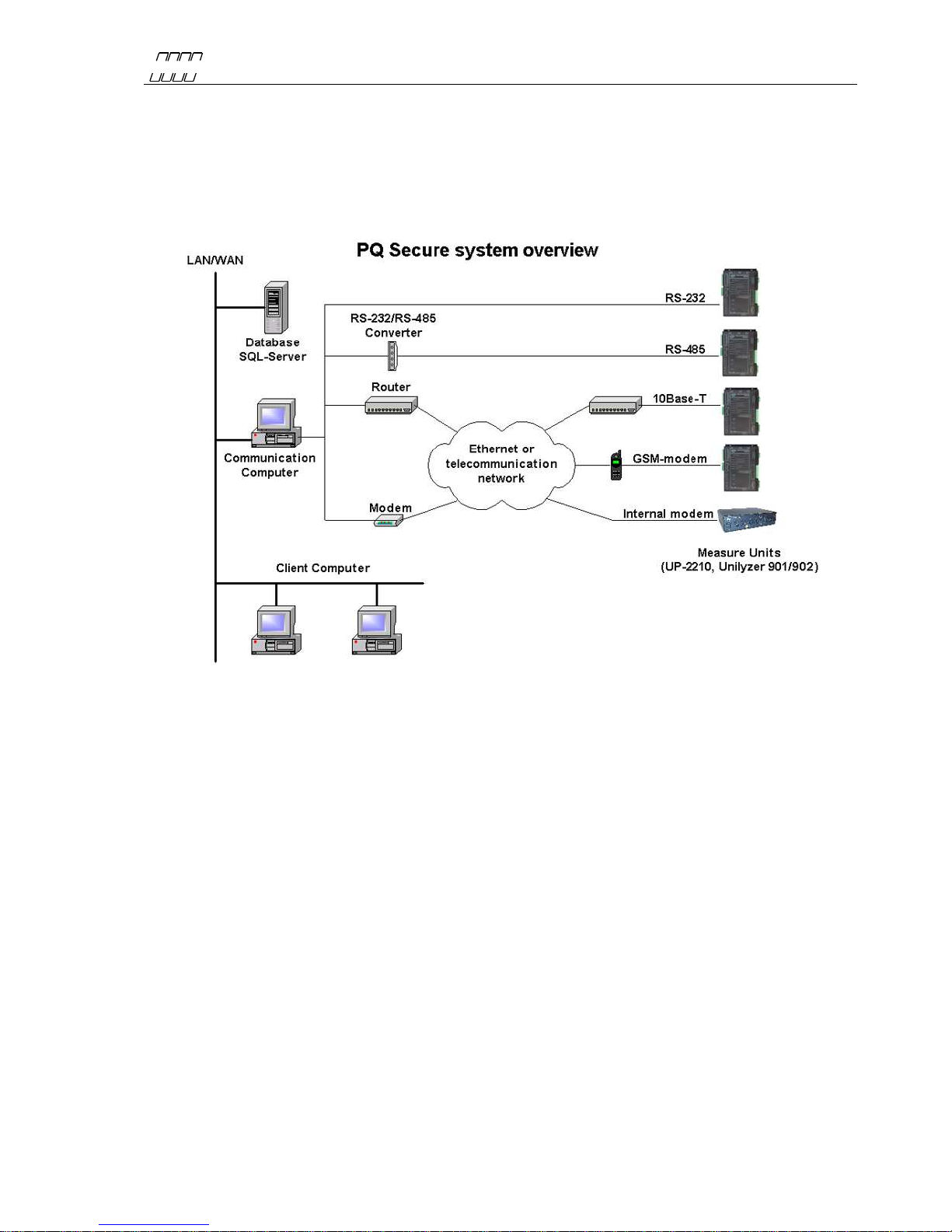
3COMPONENTS OF THE PQ SECURE SYSTEM
PQ Secure system is a collective name for a permanently installed measuring system for the
continuous monitoring of power quality in the electricity network. It consists of three parts - the
measure device, communication equipment and a computer for storing the measured data.
A PQ Secure system can have the following configuration:
PQ Secure is a highly advanced and fully automated power quality monitoring and control system-
easy to configure and use. After the system and all its meters are installed, any necessary
configuration changes can be made directly from the office, without the need to go to the installation
sites.
Figure 1
UNIPOWER
UP-2210 Hardware installation and configuration manual
9
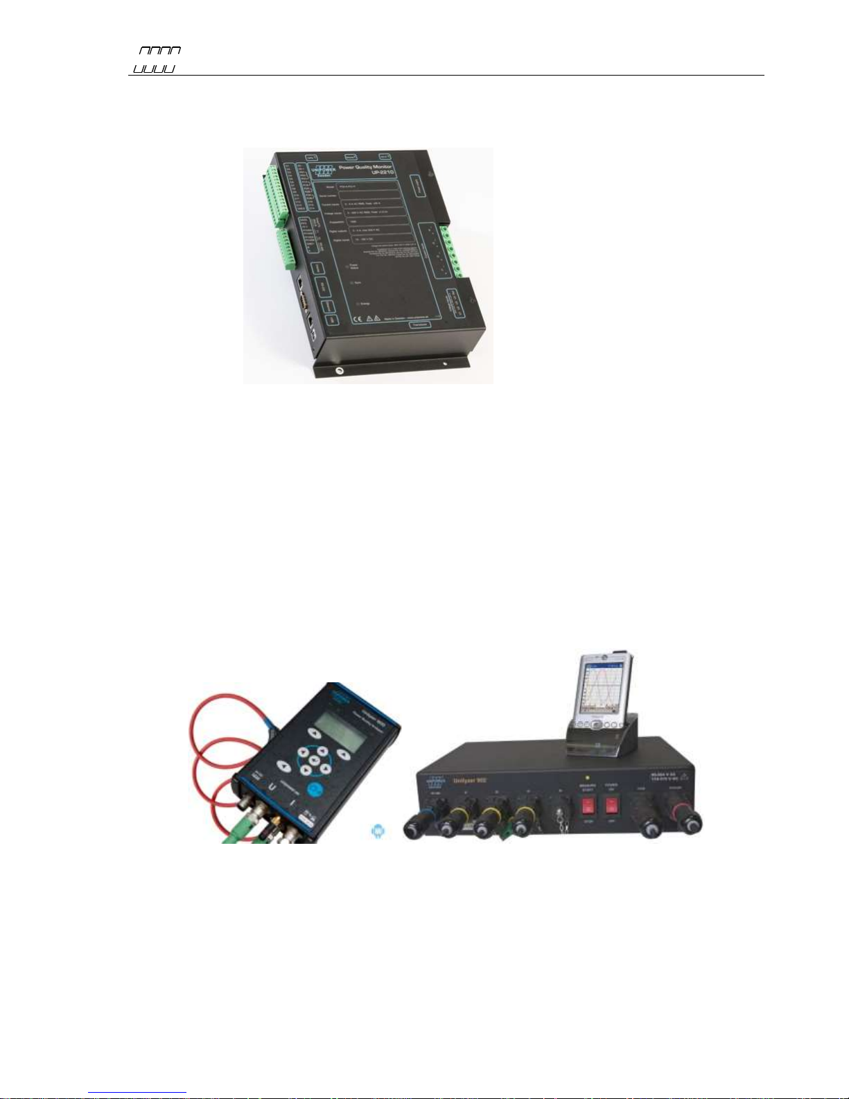
3.1 Measuring device
The measuring device UP-2210 is an advanced, 3-phase power quality and disturbance analyzer
designed for permanent installation.
3.2 Communication
All measured data is automatically transferred from the meter to the server. There are several options
for communication between the meters and the computer center. The meters may be equipped with
RS-232, RS-485, built-in modems and Ethernet ports. This means that communication is possible
using a range of media, such as a standard telephone lines, signal cables, GSM phones, local
computer networks, etc. Different meters can use different communication options within the same
system, creating a highly flexible communication solution.
3.3 Portable meter Unilyzer 900 / Unilyzer 900c / Unilyzer 902
The meters Unilyzer 902/900/900c are portable power quality and disturbance analyzers. They can
also be integrated in a PQ Secure system together with permanently installed meters.
Figure 3
Figure 2

UNIPOWER
UP-2210 Hardware installation and configuration manual
10
3.4 Software
The PQ Secure system consists mainly of four programs performing different functions. The system
is built around a Microsoft SQL server, which stores all information about the system as well as the
measure data. The client computers and communication computers later use this information when
they contact the measuring devices and when they perform analyses.
PQ Secure Main program of the system. Used to present measure data from the
SQL database, and to configure the system.
PQ Online Used to present real-time values from the meters, and to configure the
meters.
PQ Schedule Manages communication with the meters and transfers their measure
data to the SQL database.
PQSM PQ Secure System Manager. Server software, which handles a
periodic reports, limit calculations, alarms, PQ Ports etc.
PQS DB Wizard Only used when the PQ Secure database is being installed and updated.
UniLauncher Software/service used to automatically connect to meters.
Microsoft SQL Server is also needed for the operation of the system, this software is purchased
separately.
Andere Handbücher für UP2210
1
Inhaltsverzeichnis
Andere Unipower Messgerät Handbücher


